1. SCOPE
2. REFERENCE
3. DEFINITION
4. RESPONSIBILITY
5. MATERIIAL RECEIVING, STORAGE OF PIPPE SUPPORT
6. PIPE SUPPORT FABRICATION
6.1 Fabrication Work Flow
6.2 Material Marking & Identification
6.4 Material Cutting
6.5 Fit-Up & assembly of pipe supports
6.6 Welding
7. HANDLING AND CONTROL OF PRE-FABRICATED SUPORTS
8. 0 STORAGE
9. INSPECTION
10.0 RELEASING PIPE SUPPORT
11.0 DOCUMENTATION
12.0 SAFETY
Attachment 1 Risk Assessment for Support Fabrication Work Shop
Attachment 2 Support Fabrication Shop Layout Drawing
Attachment 3 General Notes
Attachment 4 Support Material
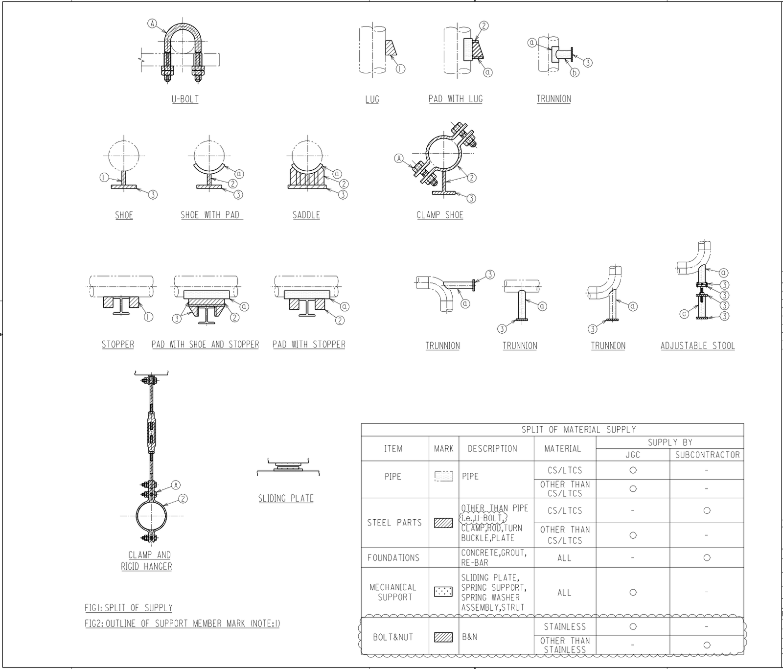
Attachment 5 Scope of Material Supply
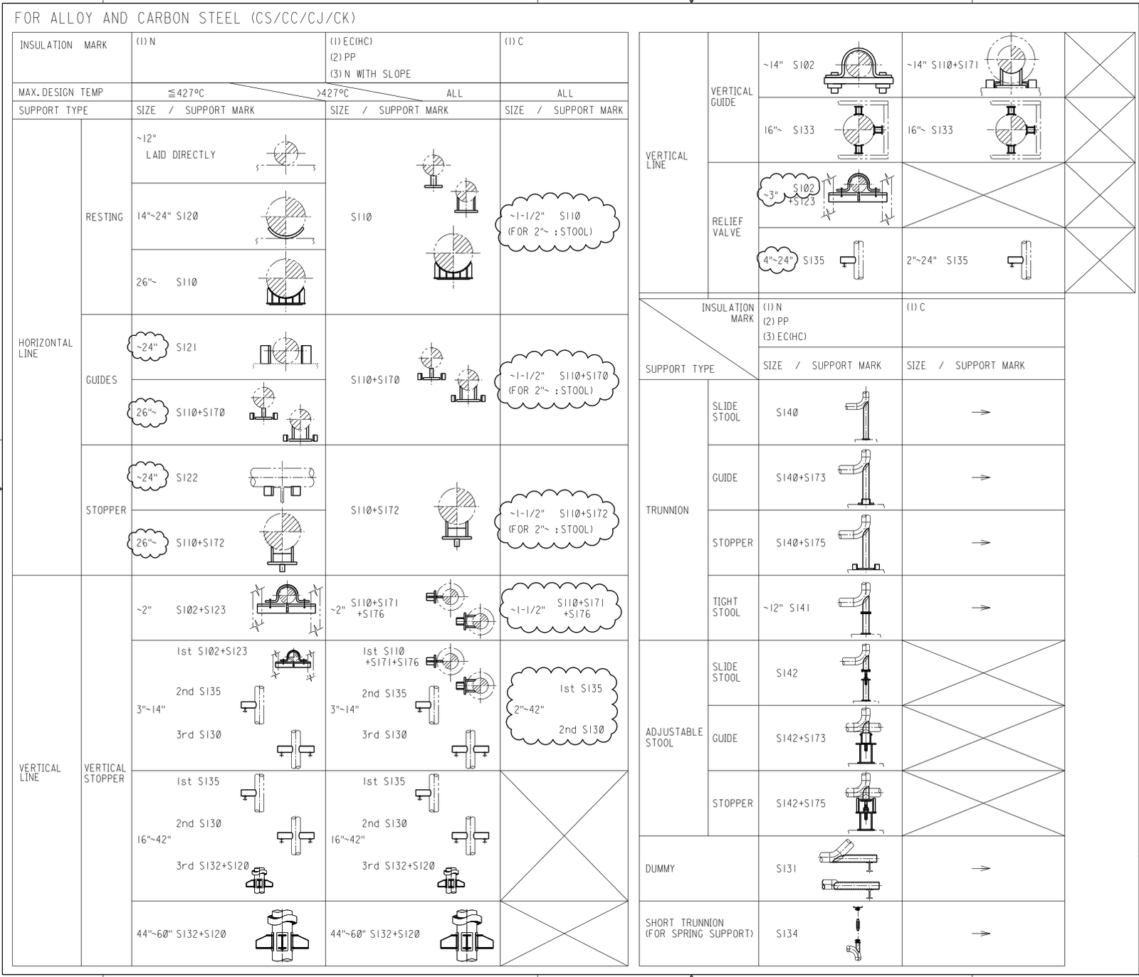
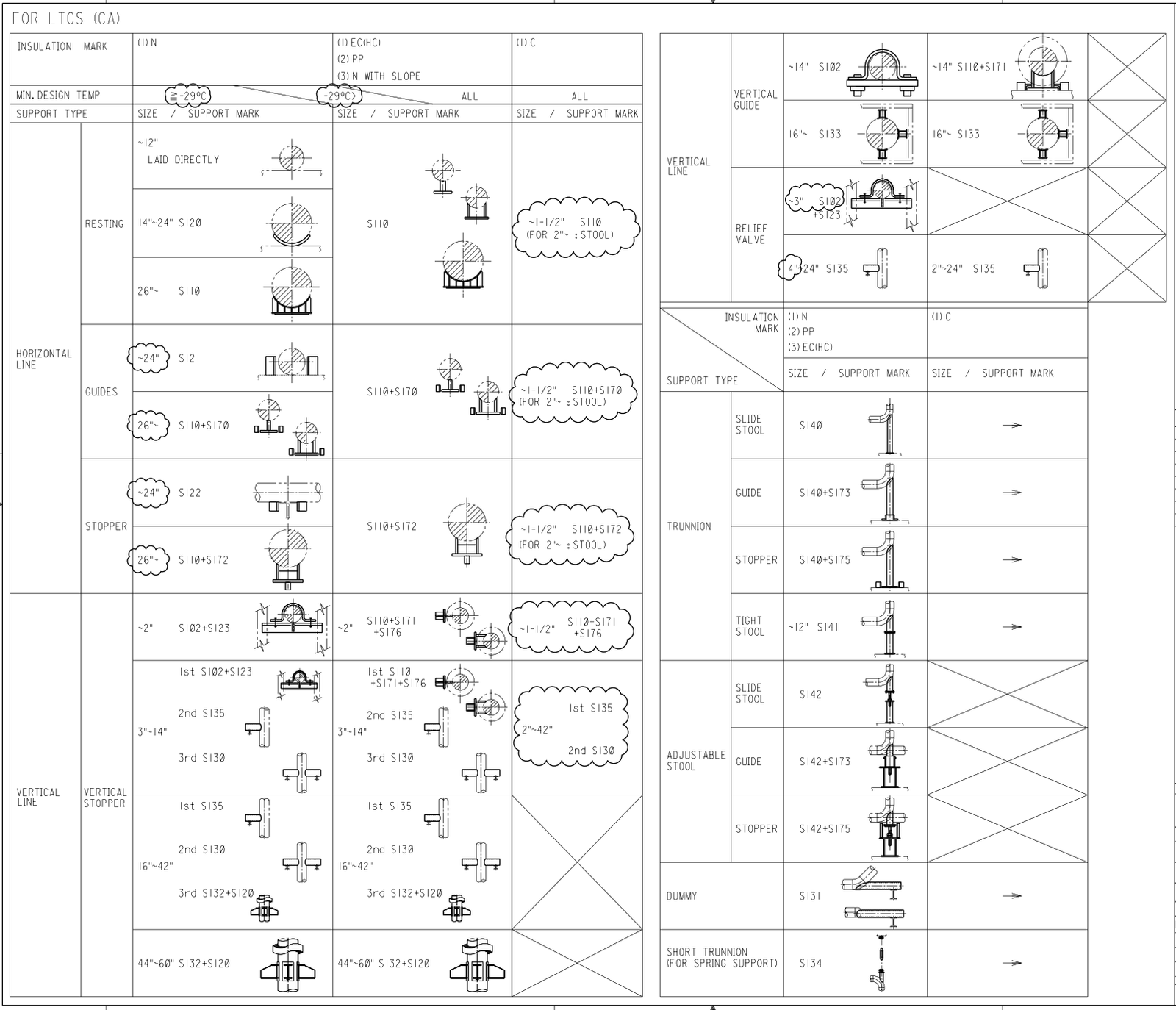
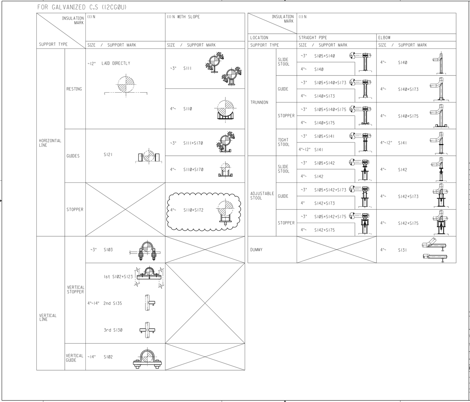
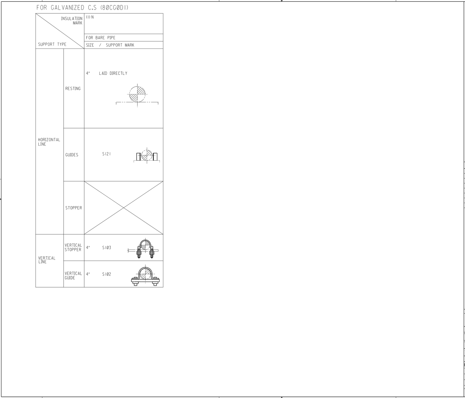
Attachment 6 Support Selection Criteria
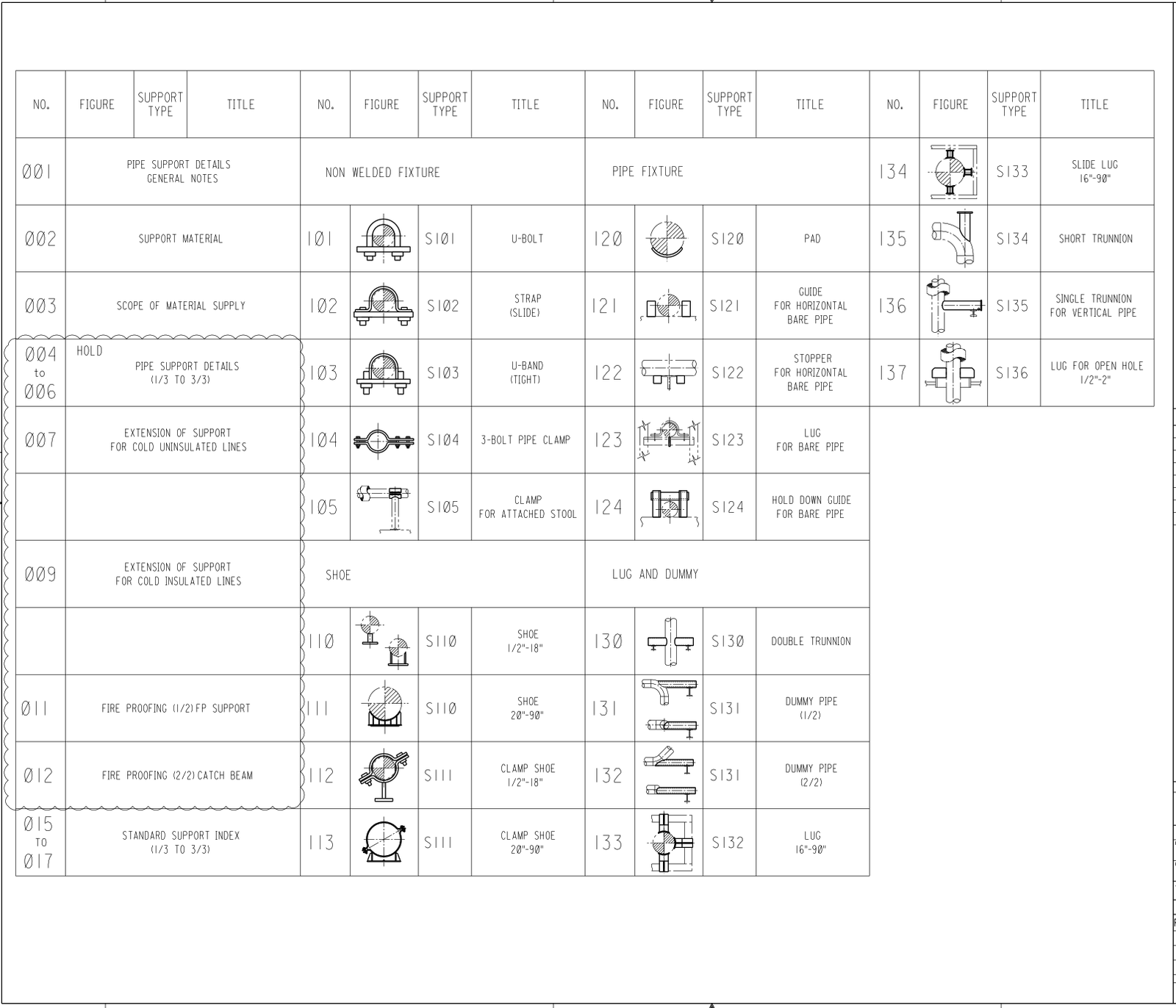
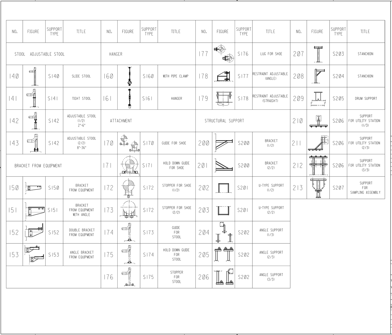
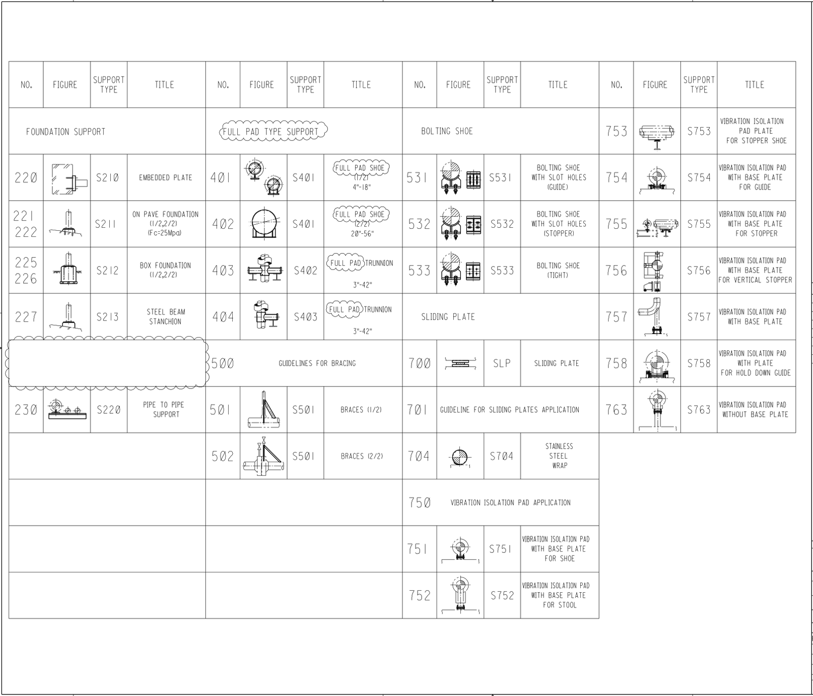
Attachment 7 Index
Attachment 8 Daily Fit-up Inspection Report
Attachment 9 Daily Welding Inspection Report
Attachment 10 Paint Request List (Support)
PIPE SUPPORT FABRICATION PROCEDURE | METHOD STATEMENT
1. SCOPE
This procedure applies to all work for fabrication and installation of pipe supports in fabrication shop for Plants and Refinery Projects.
2. REFERENCE
The piping support work shall strictly conform to the Applicable Codes, Standards and project specifications.
ASME B 31.1 Power Piping
ASME Section V Non- destructive Examination
ASME B 31.3 Process Piping
ASME Section IX Welding & Brazing Qualification
ASME D 1.1 Structure Welding Code
SAES-A-206 Positive Material Identification
SAES-L-105 Piping Material Specifications
SAES-L-110 Limitations on Pipe Joints and Components
SAES-L-132 Material Selection of Piping System
SAES-L-310 Design of Plant Piping
SAES-L-350 Construction of Plant Piping
SAES-M-001 Structural Design Criteria for Non-Building Structures
SAES-W-011 Welding Requirements for On Plot Piping
SAES-W-016 Welding of Special Corrosion — Resistant Materials
01-SAMSS-010 Fabricated Carbon Steel Piping
12-SAMSS-007 Fabrication of Structural and Miscellaneous Steel
3. DEFINITION
4. Responsibility
The following GIWI personnel shall be involved and responsible for the activities incorporated in this method statement and to ensure that all quality aspects are adhered to:
- Project Manager
- Construction Manager
- QA/QC Manager
- QC Supervisor
- Piping/Structural Engineer
- QC Inspector (s)
- Structural Foreman
4.1 Project Manager shall be responsible for the overall project control activities pertaining to this project
4.2 Construction Manager shall be responsible for the implementation of this procedure that shall maintain the required quality level at each stage of fabrication.
4.3 QA/QC Manager shall be responsible in providing technical assistance to construction project management as necessary to initiate quality enhancement and resolve quality problems throughout the organization. Monitor, provide technical assistance and resolve all quality related problems with the activities of the construction.
4.4 QC Supervisor shall perform the assigned quality assurance and quality control and inspection activities and assist the QCM. Arrange for Welder Qualification Test and issue qualification certificate to the qualified welders. Review WPS and PQR for the said activities of the project. Take regular field patrol to assure that welding quality exercised by eligible welder is maintained through overall welding activities and that the welding work strictly adheres to the job requirements. Against the non-conformance, if any found during the patrol, issue an instruction to take a corrective action.
4.5 Piping/ Structural Engineer(s) shall be responsible for the execution of correct working techniques with strict adherence to this method of statement and reference documents.
4.6 Structural Foremen shall be directly responsible for the Quality maintained by the workmen under them. They shall confirm that latest drawings, specifications, grades of materials, correct tools and equipments, etc. are used. They shall also guide the workmen in the interpretation of drawing/documents so that the work is carried out in the correct sequential manner, meeting the various in process inspection activities.
4.7 The Welding Supervisor/Foremen shall be responsible for deploying qualified welders. They shall also be responsible for ensuring that the welders withdraw electrodes as per Consumable method of statement.
4.8 QC inspectors/Welding inspectors shall be responsible for carrying out the in process inspection, visual inspection and relevant tests as per ITP’s. They shall also be responsible for maintaining the documentation and records of inspection.
4.9 Material Receipt, Storage of Pipe Support
4.9.1 The Material Controller shall receive the raw materials for the pipe support.
4.9.2 All the material will be stored in safe/secure area.
4.9.3 All the materials to be stored in a planned manner so as to easy identification of materials and issue.
4.9.4 Materials up on receipt shall be checked for quantity by ware house personnel. QC inspector to conduct material receiving inspection against the purchase order, size, quantity, material specification and material test certificate and heat number when applicable.
4.9.5 Make sure all the raw material are properly marked and recorded with its applicable identification marked and code numbers as per project requirements.
4.9.6 Pipe support shall be placed on wooden dunnage /pallets to prevent direct contact with the ground.
4.9.7 Stainless steel materials placed on pallets shall be free of carbon steel nails and galvanized wire etc.
4.9.8 Segration of Material as per Specification Material in Lay down Area as per SAES
5. Pipe Support Fabrication
5.1 Fabrication Work Flow

5.2 Material Marking & Identification
5.2.1 Stainless steel shall not be marked by stamping, but may be marked using a Vibrator-Etch tool or chemical composition acceptance marker.
5.2.2 Paints or inks may be used for marking of supports
5.2.3 Certified chloride-free marking or color coding has water soluble chloride content below 50 ppm (measured after drying) for stain steel materials.
5.2.4 Color coding for support material shall be done as mentioned below:
Carbon Steel – No color
LTCS – Orange
Alloy (P11) – Dark Blue
Alloy (P22) – Green
Stainless Steel (304/304L) – No Color
Stainless Steel (321) – Pink
Monel – Yellow
5.3 Material Cutting
5.3.1 No flame cutting is allowed on Stainless steel materials..
5.3.2 Power grinding wheels or high speed cutting wheels and or brushes which have been used for carbon steel shall not be used for the fabrication of stainless steel materials.
5.3.3 Carbon steel materials may be cut by mechanical or thermal means.
5.3.4 Cutting shall be made with suitable allowance taken into account for shape of connections and shrinkage due to cutting and welding.
5.3.5 The roughness of cut surfaces and occasional notches on edges shall be removed by machining or grinding. Cut surfaces and edges shall be left free of slag.
5.3.6 Before cutting, suitable material traceability and mark-up of cutting limits shall be done on each part of materials to be cut.
5.3. 7 Contours of all weld end preparation shall be smooth without any rough edges.
5.4 Fit-Up and Assembly of Pipe Support
5.4.1 Pipe supports shall be fabricated in accordance with the pipe support drawing.
5.4.2 All the cut materials are checked against approved Drawings and its item number.
5.4.3 If components are fitted using layouts or fixtures, it shall be checked by the QC Inspector with the applicable drawings.
5.4.4 After the fit-up, dimension and squareness shall be check by the QC Inspectors.
5.4.5 After completion of fit-up, each support shall stencil with a unique mark to make it traceable to the corresponding spools as per isometric drawing.
5.4.6 The piping are not used to support other pipes and structures without an appropriate analysis.
5.4. 7 Longitudinal weld joints of full encirclement sleeves are provided with 16 GA back-up strips prior to welding.
5.4.8 The corners of the saddle pads or reinforcing pads have rounded corners.
5.4.9 The edges of all tightly contacting surfaces on the fabricated structural supports (saddle type, Ring Girder, etc.) are completely seal welded.
5.4.10 All welds of pipe supports to the pipe wall are continuous with smooth finish.
5.4.11 Minimum fillet weld size is 3/16 inch (5 mm) for structural welds. (Seal welds may be 1/8 inch (3 mm) minimum fillet weld.)
5.4.12 Wear pads are installed at each support of Piping in hazardous services where condensation can form on the pipe, or operating within 30 m of the sea. Excluded from this requirement are low pressure systems with hoop stress at design pressure below 20% of Specified Minimum Yield Strength (SMYS) of the pipe.
5.4.13 Type and/or classification of pipe supports installed on the line conforms with the detailed design drawings and/or the Project Pipe Support Schedule.
5.4.14 Pipe supports are in full contact with supports that carry the load. This applies to the fit-up of wear pads, segmental saddles and full encirclement sleeves to the pipe.
5.4.15 Structural steel pipe used for dummy legs have open ends sealed to prevent internal corrosion.
5.4.16 A 6 mm weep hole is drilled for all dummy supports located near the base plate for all vertical dummy supports, and near the run pipe at 6 o’clock position for all horizontal dummy supports.
5.4.17 Additional dummy leg supports other than those in the design drawings are installed only without prior review and approval by Saudi Aramco SAPMT or CSD.
5.5 Welding
5.5.1 Fit-up and welding of all Pipes support materials and components for fabrication system shall be performed in accordance with approved WPS.
5.5.2 Welding shall be done for joining support members, fitting and other components unless otherwise specified on the approved design requirements.
5.5.3 Oil, moisture, rust, scale, sand, paint, metallic coatings, or other foreign matter shall be removed from the weld surface of adjacent base metal prior to welding, including any such coatings on temporary attachments or supports.
5.5.4 All the welds shall be made by qualified welders.
5.5.5 Each welding pass shall be thoroughly cleaned of slag & other foreign matter before the next pass is deposited.
5.5.6 All slag, flux, and spatter and any stray arc strikes shall be removed from the completed weld and surrounding area.
5.5. 7 Stainless steel and nonferrous materials shall be cleaned with grinding wheels or stainless steel brushes not previously used on other materials.
5.5.8 Stainless Steel Area Isolated for Support Fabrication at Shop No.1 see Attached shop Layout Drawing
5.5.9 Rejected welds shall be repaired in accordance with the welding procedure, by qualified welders as per Approved Welding Procedure Specification (WPS).
6. Handling and Control of Pre-fabricated Supports
6.1 After completion of pre-fabrication, the supports shall be cleaned and free from weld spatters, arc strikes and foreign materials on the surface of the supports.
6.2 Marking / Identification of supports, Permanently Mark or Stamp with Stenciled / Hard Punching System and Barcode shall at top of base plate one place of each support.
6.3 Upon completion of fabrication, supports shall be inspected and released for painting or storage, in accordance to Inspection and Test Plan.
6.4 No supports should be released from the fabrication shops to laydown yard, painting or site before being fully inspected and released by the QC department.
7. Storage:
7.1 Pipe supports shall be stored in their designated area in accordance with area identification coding.
7.2 Pipe supports shall be laid on wooden sleepers or other suitable material above ground level.
8. Inspection
8.1 Inspection will be carried out in accordance with approved fabrication drawings.
8.2 All welds shall have 100% visual inspection performed as per ANSI/AWS D1 .1. In addition, any arc strikes, gouges, and other indications of careless workmanship (such as surface porosity) shall be removed by grinding.
8.3 For any ‘Hold’ or ‘Witness’ points of the Contractor and/or Company, Construction shall issue Forecast for Inspection as per the form attached. This shall be followed by Application for Inspection by QC Dept.
9. RELEASING OF PIPE SUPPORTS
9.1 After required inspection has been done and accepted documentation shall be prepared, completed by the QC inspector prior to release the pipe support.
9.2 The QA/QC inspector shall prepare the pipe support release sheet for painting. See Attachment: 9
10. DOCUMENTATION
10.1 Upon completion of pipe support fabrication and/or installation, all the reports shall be documented by the QC Inspector.
11. SAFETY
11.1 Piping support fabrication and erection / installation will be undertaken in accordance with the Project Safety Manual.
11.2 All necessary PPE will be provided and worn, in accordance with the Project Safety Manual.
11.3 All lifting equipment & accessories shall be certified for their capacity and validity by Third Party which shall be color-coded
11.4 All electrical equipment shall be properly ground and color-coded.
11.5 All the workers must use their safety equipments and PPE’s.
11.6 Welding generators shall be ground.
11. 7 Ensure gas cylinders are stored vertically and tied up with chain. Ensure stickers on gas cylinders with date of filling and inspection.
11.8 Oxy-Acetylene cylinder carriage shall have partition.
11.9 Flash back arrestor shall be installed near cutting torch.
11.10 Piping Fabrication shops and site will be kept in a clean and tidy manner. Attachment 1-Details of Full Encirclement Sleeves and Saddle Pads
11.11 All workers must be provided Trainings for Hot works, lifting, Manual Handling, fire watch, TSTI and electrical safety respectively.
11.12 Job Supervisor or lead man should have a clear understanding of the job procedure and its related hazard to communicate with his co workers and labors.
11.13 Emergency contact numbers should be provided inside fabrication workshop and First Aid kit should be available at site all the times to provide first aid in case of any injury or accident.
11.14 Proper ventilation for the workers shall be provided during the hot summer season to minimize the chances of heat stress and other heat related illnesses.
11.15 Water stations shall be provided with cold water to maintain the hydration level of the workers during hot environment inside fabrication workshop.
11.16 Auto machines shall only be operated by trained and competent person. The picture of the competent person shall be displayed near the machine to check if any unauthorized workers not operate machines.
11.17 Signage and poster shall be displayed inside fabrication workshop to create a safe environment for the workers.
11.18 Adequate fire extinguishers shall be provided inside fabrication workshop to control initial fire hazards.
- Risk Assessment for Support Fabrication Work Shop.
- Support Fabrication Shop Layout Drawing.
- General Notes.
- Support Material.

- Scope of Material Supply.

- Support Selection Criteria.


- Index.


- Daily Fit-up Inspection Report.

- Daily Welding Inspection Report.

- Paint Request List (Support).