SAES-L-120 is a standard that provides design requirements for the flexibility analysis of piping systems. Here are the key points from the description you provided:
- Scope: SAES-L-120 defines the design requirements for conducting flexibility analysis of piping systems. It is intended to supplement the applicable sections of ASME B31.1, ASME B31.3, ASME B31.4, and ASME B31.8 codes.
- Applicability: This standard is applicable to both onshore and offshore unrestrained piping systems. It includes transition piping sections between underground and above-ground installations. However, it is not applicable to fully restrained aboveground or underground piping systems or offshore sub-sea pipelines.
- Non-Metallic Piping: SAES-L-120 explicitly states that it is not applicable to both aboveground and underground non-metallic process piping systems. For flexibility analysis of non-metallic piping systems, the requirements of ASME B31.3 should be followed.
In summary, SAES-L-120 provides guidelines for conducting flexibility analysis of piping systems in specific contexts, primarily focusing on metallic piping systems in onshore and offshore environments. It outlines when and where the standard is applicable and clarifies that non-metallic piping systems should follow ASME B31.3 for flexibility analysis.
To Read and Download Full Document of SAES-L-120.
SAES-L-120Piping Flexibility Analysis Technical Details
International Codes and Standards Used
American Society of Mechanical Engineers
ASME B31.1 Power Piping.
ASME B31.3 Process Piping.
ASME B31.4 Pipeline Transportation Systems for Liquid Hydrocarbons and Other Liquids.
ASME B31.8 Gas Transmission and Distribution Piping Systems.
Responsibilities and Qualifications in Piping System Design:
In the complex world of piping system design, responsibility and qualifications are paramount to ensure compliance with standards and, most importantly, the safety and reliability of the systems. This article explores the key aspects outlined in a set of guidelines regarding the responsibilities of design agencies and the qualifications of stress engineers involved in the design and analysis of piping systems.
Responsibilities of the Design Agency
Responsibilities emphasize the critical role of the design agency in the piping system’s lifecycle. The design agency’s primary duties include:
- Flexibility and Compliance Check: Ensuring that each piping system undergoes a thorough evaluation for flexibility and compliance with applicable codes. Compliance is vital to meet regulatory requirements and safety standards.
- Qualified Stress Engineer: Appointing a qualified stress engineer to conduct the design and analysis of the piping system. The stress engineer’s expertise is essential to assess and ensure the system’s structural integrity and performance.
Qualifications of the Stress Engineer
Qualifications highlight the prerequisites for a stress engineer involved in the design and analysis of piping systems. The qualifications aim to ensure that the stress engineer possesses the necessary knowledge and experience to perform their role effectively. The qualifications include:
- Engineering Degree: The stress engineer must have completed an engineering degree or its equivalent from an accredited institution. This educational background provides the foundational knowledge required for the role.
- Experience: A minimum of five years of practical experience in designing and analyzing pressure piping systems is essential. This experience equips the engineer with the insights and expertise needed to navigate complex piping challenges.
Flexibility Analysis and Compliance
Flexibility analysis reports are a critical component of the design package. These reports are recorded and submitted for review, ensuring transparency and accountability in the design process.
Flexibility analysis for piping systems must adhere to applicable code allowances and consider various operating conditions, including startup, shutdown, and transient states. The analysis should address the following key aspects:
- Preventing Failures: The piping system must have sufficient flexibility to prevent failures due to overstress or fatigue, leakages at joints, and detrimental stress or distortion in piping or connected mechanical equipment.
- Prescribed Limits: Computed pipe movement should remain within prescribed limits. Any movement should be accurately accounted for in the flexibility analysis.
- Adjacent Systems: The behavior of the piping system must be studied to ensure it does not have any adverse physical effects on adjacent systems or equipment.
In the intricate world of piping system design, the responsibilities of design agencies and the qualifications of stress engineers are instrumental in achieving compliance, safety, and efficiency. These guidelines set a standard for excellence and ensure that piping systems meet the highest standards of quality and performance. By adhering to these principles, the industry can continue to provide safe and reliable piping solutions for various applications.
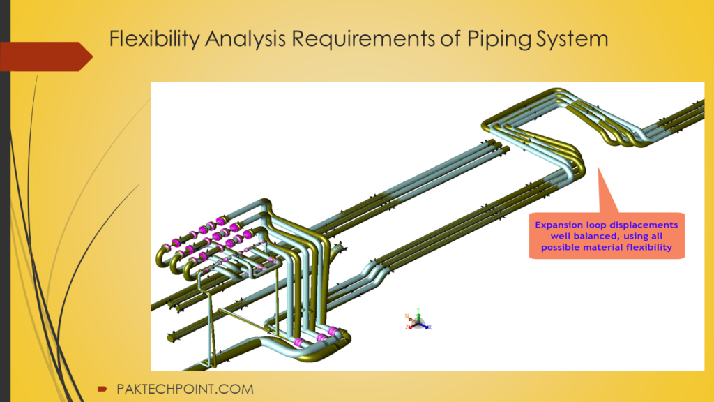
Piping Flexibility Analysis Requirements
Piping systems play a critical role in various industries, and ensuring their reliability and safety is of utmost importance. Piping flexibility analysis is a crucial aspect of this process, helping to determine the behavior of the system under different conditions. This article delves into the requirements and exemptions for piping flexibility analysis, highlighting specific situations where detailed analysis is necessary.
The requirements for piping flexibility analysis are outlined in Appendix B and paragraph 6.3. These requirements serve as guidelines for conducting a comprehensive analysis of piping systems to ensure their structural integrity and compliance with industry standards.
Exemptions from Flexibility Analysis
6.2 Some piping systems are exempt from detailed and formal flexibility analysis requirements. These exemptions are based on the specific characteristics of the piping systems and include:
- Fully Restrained Underground Lines (6.2.1): Piping systems that are fully restrained underground are exempt from both detailed and formal flexibility analysis. These lines are considered to have inherent stability.
- Fully Restrained Aboveground Lines (6.2.2): Similarly, fully restrained aboveground lines, as defined in section 4, are exempt from flexibility analysis. These lines do not require formal analysis because their structural stability is maintained.
- Duplicate Piping Systems (6.2.3): Duplicate piping systems, which are identical in design and function, do not require individual formal flexibility analysis. One calculation is sufficient to represent all duplicates.
Detailed Piping Flexibility Analysis
Detailed piping flexibility analysis is a more extensive examination that is required for specific piping systems. The following situations necessitate detailed analysis:
- Lines in Sour Gas and Sour Crude Service: Piping systems carrying sour gas or sour crude, particularly those of larger sizes, must undergo detailed flexibility analysis due to the specific challenges and risks associated with corrosive materials.
- Aboveground Flow-Lines with Axial Restraints: Flow-lines, test-lines, and trunk-lines between two axial restraints, such as camel crossings or anchors, require detailed analysis to ensure their stability under varying conditions.
- Lines with Expansion Joints: Piping systems containing expansion joints are subject to detailed flexibility analysis to account for the unique behavior of these joints during thermal expansion and contraction.
- Lines Supported by Other Lines: In cases where one line supports another, preapproval by the Chairman of the Piping Standards Committee is required for detailed analysis. Pipe sizes 2″ and smaller supported by larger pipes are exempt if stress levels comply with allowable codes.
- Lines with Internal Refractory Lining: Piping systems featuring internal refractory lining must include the increased stiffness caused by this lining in their flexibility analysis.
- Relief Systems Relieving to Atmosphere: Discharge piping from relief systems must be adequately restrained to contain thrust loads, necessitating detailed analysis to ensure safety.
- Jacketed Lines: Jacketed lines with a nominal pipe size (NPS) of 6″ and larger require detailed analysis to account for the additional complexity introduced by the jacketing.
- Lines Connected to Specific Equipment: Lines connected to fired heaters, steam generators, rotating equipment suction and discharge nozzles, air-cooled heat exchangers, reactors, and pressure vessels and tanks of specified sizes must undergo detailed flexibility analysis to ensure their compatibility and performance.
Piping flexibility analysis is a critical aspect of ensuring the reliability and safety of piping systems. By adhering to the specified requirements and exemptions outlined in industry standards, engineers and designers can make informed decisions about when detailed analysis is necessary to address specific challenges and risks associated with various piping systems. This commitment to analysis and compliance enhances the overall integrity of piping systems across different industries.
Design Conditions and Load Analysis for Piping Flexibility
The integrity and reliability of piping systems are paramount in various industries, making it essential to consider various design conditions and load scenarios during the analysis and engineering phases. This article explores key design conditions and load factors that must be considered when conducting piping flexibility analysis.
Design Conditions
7.1 Temperature Range
Temperature fluctuations can significantly impact piping systems, leading to thermal expansion and contraction. Therefore, the analysis should encompass the entire temperature range defined by the design code, accounting for thermal expansion between the minimum and maximum temperatures.
7.2 Specific Considerations
In addition to the standard temperature range, the following conditions must be considered during detailed piping flexibility analysis:
a) Steam Out Condition (for Lines Connected to Vessels): Lines that cannot be disconnected during steam out procedures must be analyzed to assess their response to this high-temperature condition.
b) Solar Radiation Effect: When pipes are exposed to solar radiation, they can experience temperature increases of up to 160°F in empty conditions. This effect should be factored into the analysis to address potential thermal stresses.
Load Conditions
The performance and safety of piping systems depend on their ability to withstand various loads and conditions. Design agencies must identify load combinations that the piping system may encounter throughout its service life. The following load cases are considered minimum requirements for analysis:
8.1 Sustained Load: This load case includes factors such as internal pressure, the weight of the pipe itself, the contents it carries, additional piping components, insulation weight, and other sustained loads.
8.2 Thermal Load: The thermal load scenario covers the entire temperature range and accounts for any resulting thermal displacements. It is crucial to evaluate how temperature variations affect the system’s stress and displacement.
8.3 Operational Case: This load case considers the operational displacement of the piping system and the loads exerted on any attached equipment during normal operation.
8.4 Hydrotest Load: During hydrostatic testing, the weight of the test medium (usually water) is applied to the piping system. This load condition ensures that the system can safely withstand the test without excessive stress.
8.5 Occasional Load: This case addresses sustained loads combined with short-duration upset conditions, such as wind or earthquakes. Notably, wind and earthquake loads should not be simultaneously applied in the stress analysis.
8.5.1 Wind Loads: For lines with a nominal pipe size (NPS) of 10″ and larger at heights of 10 meters or more, wind loads must be considered in the stress analysis. Environmental loads that may affect piping design are outlined in SAES-A-112.
8.5.2 Earthquake Loads: Earthquake loads should be calculated in accordance with UBC Section 2336 and SAES-A-112, ensuring that the piping system can withstand seismic events without structural failure.
Design conditions and load analysis are crucial aspects of ensuring the reliability and safety of piping systems. By considering temperature ranges, specific conditions, and various load cases, engineers and designers can develop piping systems that meet industry standards and perform effectively under all anticipated scenarios. This comprehensive analysis enhances the overall integrity and longevity of piping systems across different industries.
Special Requirements and Load Limitations in Piping Design
Piping systems are subjected to various external loads and conditions that can impact their performance and safety. To ensure the reliability and integrity of these systems, engineers and designers must adhere to special requirements and load limitations. This article explores specific considerations and limitations that play a crucial role in the design and analysis of piping systems.
1. External Load Limits on Equipment Nozzles
The loads exerted by piping on equipment nozzles should not exceed the maximum allowable limits recommended by equipment manufacturers or as stipulated in applicable industrial codes. These limits ensure the safety and integrity of the equipment-nozzle connections.
2. Piping Systems Subjected to Water or Steam Hammer
Piping systems vulnerable to water or steam hammer must undergo a thorough analysis to determine the forces generated during these events. Suitable support systems should be designed to mitigate the impact of water or steam hammer, safeguarding the integrity of the piping system.
3. Pressure Relief Valves and De-pressuring Systems
The analysis of pressure relief valves and de-pressuring systems involves several critical aspects:
a) Relief Discharge Reaction: The reaction forces resulting from open relief valves must be considered.
b) Piping Flexibility: The analysis should account for thermal expansion during hot relief or contraction during cold relief.
c) Dynamic Loads: Dynamic loads from worst-case flow conditions should be assessed to ensure the system’s structural integrity during relief events.
4. External Localized Loads
Stress analysis should incorporate circumferential bending stresses in the pipe wall arising from external loads, including supports, anchors, soil pressure, or other external forces. An exception is made for loads transmitted through a full encirclement sleeve welded to the pipe.
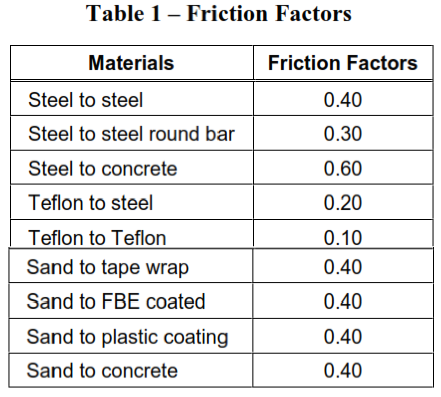
5. Friction Forces
Friction forces exerted by supports and guides should be considered as external localized loads. If experimental or vendor data is unavailable, friction factors provided in Table 1 should be used for flexibility calculations.
Limitations on Load Cases
Several limitations and considerations apply to specific load cases:
1. Restrained Pipelines: Design and construction of fully restrained pipelines should account for tie-in temperature ranges and anticipated temperature variations.
2. Lined Piping: Cement-lined piping should adhere to specified maximum allowable bending stresses in the steel, especially when considering the equivalent moment of inertia of the lined pipe.
3. Branch Connections: Branch connections to buried piping must have the flexibility to withstand axial movement without overstressing the connection. For aboveground piping, thermal expansion and branch line effects should be considered.
4. Expansion Joints: Swivel joints, expansion joints, and similar devices should not be used to reduce the stiffness of piping systems or equipment nozzle loads in hazardous services, except for specific fluid service categories defined in ASME B31.3.
5. Differential Settlement: When designing or modifying plants, the potential for differential settlement between foundations must be considered in pipe stress calculations. Settlements exceeding ½” should trigger a thorough analysis to ensure system adequacy.
6. Cold Spring: The use of cold spring in the analysis is not permitted, ensuring that the piping system behaves as expected under load conditions.
Adhering to special requirements and load limitations is essential for designing safe and reliable piping systems. Engineers and designers must consider external loads, equipment connections, pressure relief, and various load cases to ensure the structural integrity and longevity of these critical systems. Careful analysis and compliance with industry standards are paramount in achieving these goals.