PROCEDURE FOR INSTRUMENT BRANCH CABLE TRAY INSTALLATION
General Requirements
- All cable trays and supports will be installed as shown on EPC approved design construction drawings and located to avoid interferences with other facilities. Interferences shall be notified to contractor for solution and final disposition. The final branch cable tray route shall be decided by subcontractor Field Engineer in accordance with the site condition.
- Subcontractor shall submit actual cable tray drawing after installation for As-built.
- All installation requirements and tolerances shall be in accordance with the technical specification, the latest construction drawings and the applicable documents shall be SAES-J-902, NEMA VE-2, SAES-P-104 and SAES-P-111.
- The channel cable tray shall be designed, manufactured and marked in accordance with NEMA VE 1 – 2002.
- As per SAES-J-902 Section 9.8.2 Channel cable tray width shall be 3, 4, or 6 inches with a minimum loading depth of 1 ¼ inch.
- The channel cable tray material shall be copper-free aluminum (aluminum with a maximum of 0.4% copper) SAES-J-902, 9.8.1.
- The channel cable tray system shall be installed with the manufacturers standard fittings, clamps, hangers, brackets, splice plates, reducer plates, blind ends, connectors, and grounding straps.
- The channel cable tray system shall be installed with flanged covers.
- The ventilated strait sections shall have slots (approximately 3/16″ x ½”) to facilitate the use of cable ties to secure the cable(s). The slots shall repeat every 12-18 inches.
- The ventilated strait sections shall have splice holes, repeating every 12-18 inches to simplify field modifications.
- All fasteners (i.e., nuts, bolts, washers, etc.) used to connect and assemble the channel cable tray system shall be 316 SS.
- The channel cable tray system shall be free from burrs or other sharp projections that could cause damage to the cable jacket during installation.
- Cable tray systems shall not be used in hoist ways or where subject to severe physical damage as per NEC 392.12.
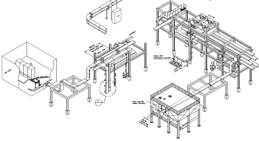
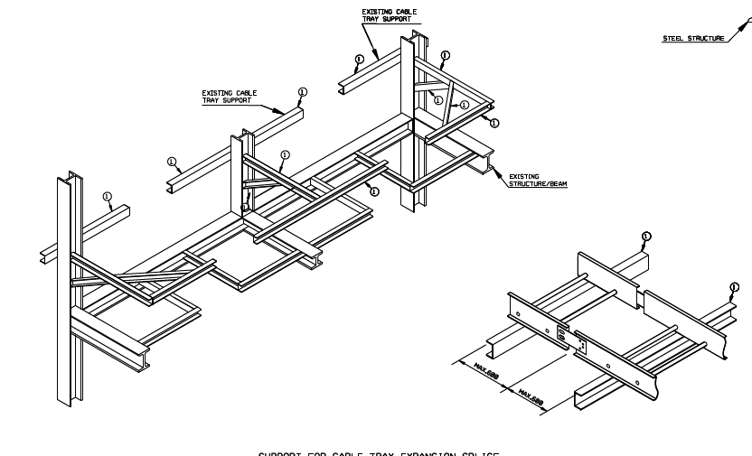
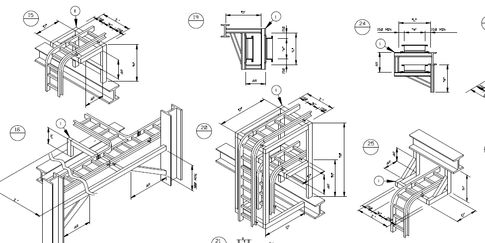
- Cable trays shall be installed as per typical installation drawing. see below figure
- Sufficient space shall be provided and maintained about cable trays to permit adequate access for installing and maintaining the cables as per NEC 392.18(F).
- Cable tray run shall not have any sharp edges or projection as per NEC Article 392.100 (B)
- Cable tray shall be a complete run prior to installation of cables.
- Cable tray installed out door shall have a complete cover for protection of possible accumulation of dust and foreign materials.
- Instrument channel cable tray distance to power cable shall be followed in signal separation table of SAES-J-902 Section 14.
- This Method Statement is intended as a practical guide for proper installation of cable tray systems. However, the spread of fittings, types, finishes and installation requirements is considerably large for inclusion in this Method Statement.
- Competent and qualified persons familiar with standard electrical construction practices, electrical equipment, and safety of electrical wiring systems will perform the work here under described.
- In order to install the cable tray supports, required elevation from the floor to the bottom of the cable tray will be found and a level line with a laser or a nylon string established.
- Where working on a platform or gratings for penetration tray, complete the hole with kick plate as per project specification.
Branch Cable Tray Supports.
- Install necessary supports for cable tray as per installation detail. All permanent materials (including fabricated supports), consumables, construction area and resources shall be prepared and checked prior to installation works and shall be approved by the clients.
- Supports for cable tray shall be strong enough to overcome the loads associated with future cable additions or any other additional loads applied to the cable tray.
- All field cut on galvanized steel supports shall be touched up with approved paint primer immediately or as manufacturer’s instruction.
- Supports shall be provided to prevent stress on cables where they enter another raceway or enclosure from cable tray systems.
- Location of supports for cable tray systems shall be in accordance with the recommendations of NEMA VE 2.
- Splice plates (joints) shall not be located over the supports, and shall be located between supports and quarter points.
- No more than one splice shall be located between two adjacent supports.
- The cable tray shall not be supported from process piping.
- Cable tray fill shall comply with NEC article 392.
- Splice plates (joints) shall not be located over the support, and shall be located between support and quarter points. (SAES-P-104, Section 9.5)
- No more than one splice shall be located between two adjacent supports (SAES-P-104, Section 9.5).
- Cable tray shall not be supported from process piping (SAES-P-104, Section 9.5).
- Cable tray fill shall comply with NEC article 392 (SAES-P-104, Section 9.5).
Grounding and Bonding
-
- Branch cable trays end shall be bonded and connected to the stanchion and other support.
- Electrical continuity can be achieved by cable to steel structure through equipment fixing bolts. For specific areas requiring bonding for electrical continuity followed project specification.
- Jumpers shall always be sized to meet project requirements and or the manufacturer’s instructions.
- Place screw head on inside of branch cable tray, put the jumper outside of branch cable tray, add flat washer and locknut, then tighten.
- Cable tray shall be grounded as defined in SAES-P-111 Section 7, 8, and 9 and NEMA VE-2 Section 4.7.
magnificent post, very informative. I’m wondering why the other specialists of this sector do not realize this. You should proceed your writing. I am sure, you have a great readers’ base already!