1. PURPOSE
2. APPLICATION
3. SCOPE
4. DEFINITIONS
5. REFERENCE
6. MOBILIZATION PLAN FOR WORK FORCE
7. KEY PERSONNEL RESPONSIBILITIES
8. MATERIALS
9. WORK PROCEDURE
10. TEMPORARY WORKS
11. QA/QC INSPECTIONS
12.SKETCHES
13. HSE REQUIREMENTS
1. PURPOSE
The purpose of this method statement is to provide procedure, work sequence and guidance for safe execution of roof water proofing system work to be carried out with accordance to project specification, Aramco standards, IFC drawings, technical specification and related international standard including project safety requirement.
2. APPLICATION
Application of this method statement is for Roof water proofing system of project buildings.
4. DEFINITIONS
Method Statement: A written document that gives specific instructions on how to safely perform a work-related task, or operate a piece of Plant or equipment.
5. REFERENCES
5.1 Project Specification
a. IFC Drawings VA-539833-003 OF1 (D-100-134A-103_0F1)
b. IFC Drawings VA-539881-002 OF1 (D-140-134C-111_0F1)
c. IFC Drawings VB-529361-001 0F1 (D-100-1348-004_0F1_0010)
d. IFC Drawings VA-539902-002 OF4 (D-140-134D-105_0F4)
e. IFC Drawings VA-539924-002 OF1 (D-100-134F-102_0F1)
f. Approved MAR T-AL-DW-0236 Material Submittal of Water Proofing System for Roof Slabs (RCC & Pre-Cast)
5.2 Saudi Aramco Engineering Standard
a. SAES-M-100 : Saudi Aramco Building Code
b. SATIP-M-100-02 : Waterproofing of Roof Slabs
C. SAIC-M-1012 : Waterproofing Roofs Receiving and Storage Inspection.
d. SAIC-M-1014 : Waterproofing Surface Preparation & Waterproofing Layer Installation Inspection (EPDM or Modified Bitumen membrane systems or TPO or PVC membrane and Insulation)
e. SAIC-M-1018 : Leak-Proof Testing/Final Inspection
f. SATR-M-1014 : Roof Flood Testing
5.3 Related International Code
a. ACI 318 – Building Code Requirements for Structural Concrete
b. ASTM C 578 – Standard Specifications for Rigid Cellular Polystyrene Thermal Insulation
c. ASTM D 4637 — Standard Specifications for EPDM Sheet use in Single-Ply Roof Membrane
d. ASTM D6369 Standard Guide Design of standard flashing Detail for EPDM
e. ASTM D 5957 — Standard Guide for Flood Testing
6. MOBILIZATION PLAN FOR WORK FORCE
The numbers of manpower/labor to be used during the activities have been identified in the manpower histogram. Contractor shall mobilize following personnel in compliance with work progression.
• Foremen
• Group Leaders
• Skilled Membrane Applicators / Masons.
• Helpers
Site Engineers and QC Engineers shall be assigned to oversee the entire roof water
proofing scope of work.
7. KEY PERSONNEL RESPONSIBILITIES
7.1 SITE MANAGER
Site Manager is responsible to provide the site with appropriate site teams and resources to ensure that work are done in accordance with the project quality requirements.
7.2 CONSTRUCTION MANAGER
He is responsible to ensure the full implementation of this method statement and identify the requirements and maintain sufficient resources for the effective accomplishment of the scope of work for repair works and responsible for implementing HSE.
7.3 SITE ENGINEER/ SUPERVISOR
He is responsible to ensure full compliance of all foreman, workers and helpers within the project requirements and specifications. Confirm the availability of all materials, tools, equipment, and required Personnel who will carry out the work.
7.4 QC MANGER/ SUPERVISOR
He is responsible to ensure the full implementation of the required minimum quality requirements, Procedures and maintain the required documentation as per applicable company inspection and test Plan for the final acceptance and handover of document.
7.5 QC INSPECTOR
He is responsible to conduct daily surveillance and inspections as necessary in accordance with this procedure and project quality requirement. Prepare quality control records and secure readiness of completed activity for final acceptance, secure the QC documentation which is required for final Handover
7.6 SAFETY MANAGER/SUPERVISOR
The Safety supervisor ensures that all safety management will enforced in a ways to prevent injury to personnel, damage to Plants and/or equipment by Fires. He should provide written instruction to established work method, explain the sequence of operation, outline the potential hazards at each stage and indicate precaution to be adopted and the Safety supervisor shall visibly demonstrate the priority of safety in all activities, including setting a good personal example. He is responsible and accountable for the proper performance of field and the competency of the safety officers under his authority. He can stop the work that deem to be unsafe and can immediate corrective action as needed.
7.7 WORK PERMIT RECEIVER
The work permit receiver shall be the authorized personnel for all the work permit related activities concern and he shall be the responsible channel for COMPANY. If necessary trial can be conducted to read the scenario of the work and obtain permits. The issuer and receiver both are the key personnel for complete execution of the work. As well as the internal work permit coordinator shall be the responsible senior person for guiding and granting work permit through company for all site activities. The other internal premises work permit shall be issued from DAEWOO.
8. MATERIALS
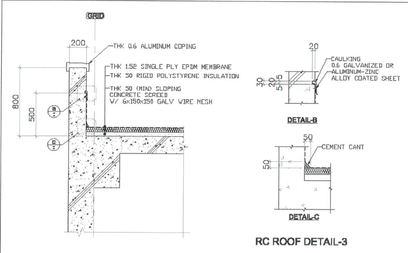
The selected water proofing system consists of:
– EPDM loose laid Membrane sheet, T=1.52mm.
– Insulation Board, T=50mm Rigid Polystyrene Insulation.
– Light Weight Concrete Slopping Screed, Thick. = 50mm (Min.) included with
(6x150x150) mm Galvanized Wire mesh.
– 0.6mm Galvanized or Aluminum-zinc alloyed coated sheet.
-Essco foam Sheets Thick. 50mm, 100mm inside screed.
9. WORK PROCEDURE
The following are work procedure general condition:
• Ensure all necessary personnel, materials, equipment and other services required for the work execution are in place and work place is clear and safe.
• Sufficient materials, plant and skilled and unskilled labor are available to ensure waterproofing application system is in continuous process.
• All health, safety and environmental rules and regulations shall be strictly adhere and must be put into practice to avoid accidents and damage during the execution of roof waterproofing.
9.1 Roof Water Proofing System
9.2 Essco foam Sheets
After satisfactory completion of concrete roof slab surface, single layers of 50 mm thick (3 Three Layers, 150 mm thick in total) essco foam sheets will be laid mechanically fastened by means of plates and screw as per accordance with the manufacture procedure and instructions.
9.2 Slopping Concrete Screed
Establish the elevation to control the slope to the drain in accordance to the approved IFC drawing and standard. A single layer of galvanized welded wire fabric 150x150x6 mm will be laid as screed reinforcement and to control cracks on the smooth finish floor of the roof slab. Ensure that the poured screed will be cured 3 days prior to installation of insulation board.
9.3 Insulation Board
After satisfactory completion of light weight sloping screed concrete, single layer of 50 mm thick rigid polystyrene insulation with glass fiber one sides will be laid mechanically fastened by means of plates and screw as per accordance with the manufacture procedure and instructions.
9.4 EPDM Membrane Sheet
• Internal corners shall be suitably dressed first with “Sure-Seal” E.P.D.M membrane. Then reinforced with extra piece layer of “sure-Seal” Elastoform Flashing of uncured ‘EPDM; 0.060″ thick, and sealed around with “sure-Seal” lap sealant.
• Roof drains shall be suitably dressed around with “Sure-Seal” E.P.D.M and sealed with “Sure-Seal” Water cut-off mastic.
• “Sure-Seal” E.P.D.M membrane overlaps shall be 100mm width, first cleaned with “Sure-Seal” Splice wash, seamed together with “sure-Seal” EP-95 self-healing Splicing Cement and sealed with “Sure-Seal” lap Sealant protection.
• Insert a new foam backing rod having a diameter grater then joint followed by fixing masking tape at both sides of the joint. Pouring heavy duty single component of polysulphide sealant “Polyseal P.S”. and single layer of Sure-Seal EPDM membraned dressing and field fabricated aluminium capping as per manufacture recommendation
9.5 Extruded Aluminium Counter Flashing:
• Installation of aluminium flashing will be fixed on wall where in termination of the waterproofing membrane in bonded on the wall.
• The gap was produce due to the summation of all waterproofing element on wall skirting will be sealed with weather proofing sealant.
9.6 Flood Testing:
Flood test shall be carried out for a period of 24hours to test the water proofing system is leak free. Restrict water run-off from membrane area by plugging drains and creating dams or dikes.
Flood the entire area to a depth of 100 mm from the highest point of elevation and observed for 24 hours. Any punctured or defective area shall be marked and immediate repair as per manufacture instruction. Re-testing shall be done upon completion of repair and observation will be 24 hours. Flood testing will be carried out as per SATR-M-1014.
10. Temporary Works
10.1 Barricades & Sign Boards:
Barriers will be erected in coordination with safety department to provide protection against Hazards and danger, hazardous work areas in all cases where hazard or danger will exist for a Period longer than 8 hours. Barricade will be marked “RED” and “WHITE” to increase visibility of the barrier and highlight the hazard within the area.
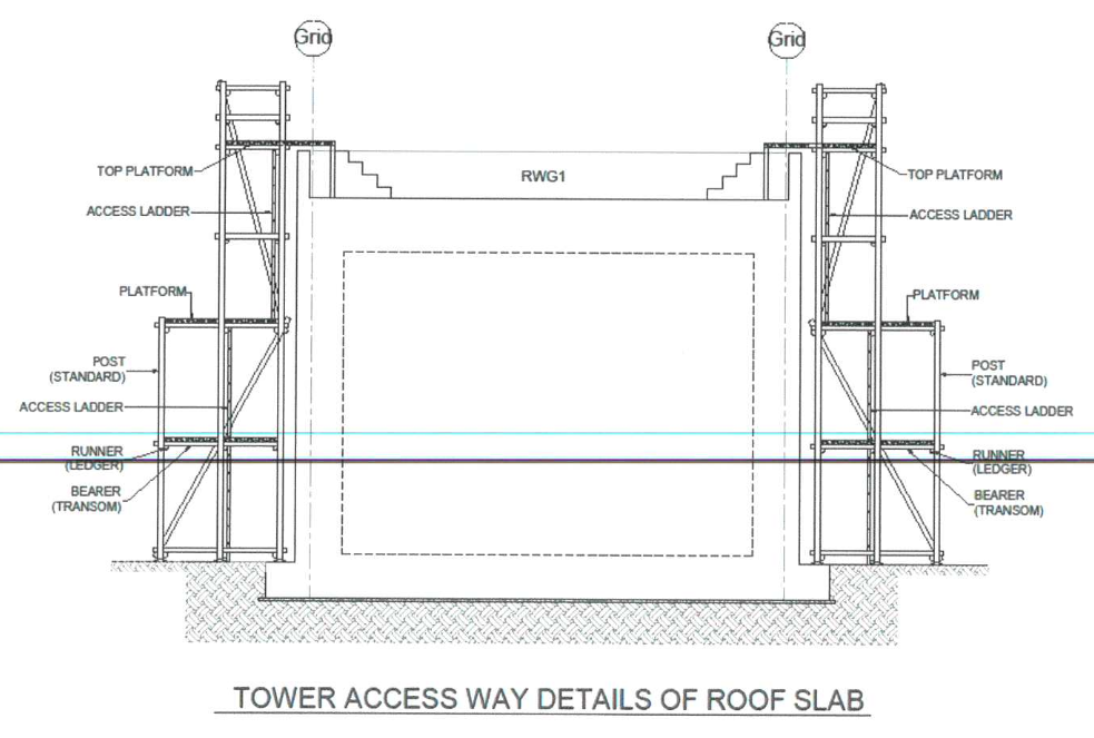
10.2 Scaffolding:
Scaffolding will be erected to area to facilities area which require height access. Scaffolding shall be erected by trained and experience scaffolding erectors with the supervisor. Scaffolding material to be used are those inspected and approved to be use at site.
Erected scaffolding will be inspected and approved by scaffolding inspector and proper tagging will be used to identify the scaffold of its completeness.
11. QA/QC Inspection
Inspection & testing: The result of inspection shall satisfy COMPANY specifications (including related International standards/ codes) & submit RFI (Request for Inspection). Inspection format shall refer to approved COMPANY’s ITP and approved related formats.
12. SKETCHES
12.1 Plot Plan for Scaffolding (Tower for Access Way):
12.2 Sketch of Water Proofing System (Pre Cast Slab & Concrete Slab):
Sketch No. 1 (Pre Cast Slab)

Sketch No. 2 (Concrete Slab)