Following topics to be discussed here for Secondary Containment, Retention and Evaporation Pond Structures.
1. SCOPE
2. REFERENCES
3. SECONDARY CONTAINMENT SYSTEMS
3.1 Tanks Containing Hydrocarbons
3.2 Retention and Evaporation Pond Structures
3.3 Conceptual Design of Secondary Containment Systems
3.4 Design and Construction of Secondary Containment Structures
4. LINER AND PROTECTIVE COATINGS
4.1 Liner
4.2 Protective Coating Systems
5. LEAK DETECTION AND MONITORING SYSTEM
5.1 General
5.2 Visual Inspection
5.3 Inventory Monitoring
5.4 Electronic Point Monitoring
5.5 Continuous or Area Monitoring
6. CATHODIC PROTECTION (CP) SYSTEM
6.1 Design
6.2 Materials
6.3 Installation
6.4 Testing and Inspection
6.5 Operation and Maintenance
7. LINERS (GEOMEMBRANES)
7.1 High Density Polyethylene (HDPE) Liner
7.2 Chlorosulfonated Polyethylene (CSPE-R) Liner
7.3 Polyvinyl Chloride (PVC) Liner
FIGURE 1 – Onground Storage Tank (OST) with Ringwall Foundation
FIGURE 2 – Onground Storage Tank (OST) with Mat Foundation
FIGURE 3 – Onground Storage Tank (OST) with Earth Foundation
FIGURE 4 – Double Bottom Onground Storage Tank (OST) with Earth Foundation
FIGURE 5 – Buried Liner
FIGURE 6 – Double Wall Tank
FIGURE 7 – Double Wall Tank
FIGURE 8 – Concrete Vault
FIGURE 9 – Partial Height Concrete Vault
FIGURE 10 – Secondary Containment for Retention and Evaporation Pond
10A. Pond Lined with Elastomeric Membrane
10B. Underdrain Arrangement for Leak Detection
10C. Ground Resistivity Pins for Leak Detection
TABLE I – Liner Material Properties
TABLE II – HDPE Resin and Extrusion Rod Properties 19
TABLE III – HDPE Liner (Smooth) Properties 20
TABLE IV – CSPE-R Liner Properties
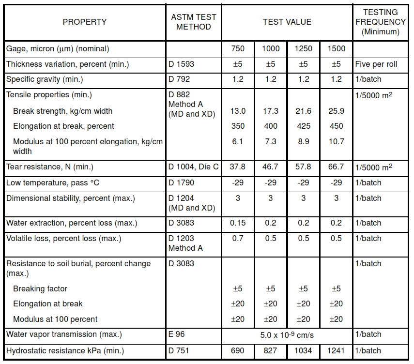
TABLE V – PVC Liner Properties
Secondary Containment, Retention and Evaporation Pond Structures
1. Scope
This article is for the design and installation of secondary containment, retention and evaporation pond structures.
2. References
Reference is made in this article to the following documents.
American Concrete Institute (ACI)
201.2R Guide to Durable Concrete
223R Standard Practice for the Use of Shrinkage-Compensating Concrete
318M Building Code Requirements for Structural Concrete
350R Environmental Engineering Concrete Structures
515.IR Use of Waterproofing and Other (Dampproofing, Protective, and Decorative) Barrier Systems for Concrete
American National Standards Institute (ANSI)
ANSI/ASME B31.3 Chemical Plant and Petroleum Refinery Piping
ANSI/IEEE 980 Guide for Containment and Control of Oil Spills in Substations
American Petroleum Institute (API)
650 Welded Steel Tanks for Oil Storage
American Society for Testing and Materials (ASTM)
D 413 -Test Methods for Rubber Property – Adhesion to Flexible Substrate
D 638 – Test Method for Tensile Properties of Plastics
D 751 Test Method for Coated Fabrics
D 792 Test Methods for Density and Specific Gravity of Plastics by Displacement
D 882 Test Methods for Tensile Properties of Thin Plastics Sheeting
D 1004 Test Method for Initial Tear Resistance of Plastic Film and Sheeting
D 1203 Test Methods for Volatile Loss from Plastics Using Activated Carbon Methods
D 1204 Test Method for Linear Dimensional Changes of Nonrigid Thermoplastic Sheeting or Film at Elevated Temperature
D 1238 Test Method for Flow Rates of Thermoplastics by Extrusion Plastometer
D 1248 Specification for Polyethylene Plastics Molding and Extrusion Materials
D 1505 Test Method for Density of Plastics by the Density – Gradient Technique
D 1593 Specification for Nonrigid Vinyl Chloride Plastic Sheeting
D 1603 Test Method for Carbon Black in Olefin Plastics
D 1790 Test Method for Brittleness Temperature of Plastic Sheeting by Impact
D 2136 Test Method for Coated Fabrics
D 3083 Test Method for Flexible Poly Vinyl Chloride Plastic Sheeting for Pond, Canal and Reservoir
D 3895 Test Method for Oxidative-Induction Time of Polyolefins by Differential Scanning Calorimetry
D 4218 Test Method for Carbon Black Content in Polyethylene Compounds by the Muffle-Furnace Technique
D 4833 Test Method for Index Puncture Resistance of Geotextiles, Geomembranes, and Related Products
D 5199 Test Method for Measuring Nominal Thickness of Geotextiles and Geomembranes
D 5397 Test Method for Evaluation of Stress Crack Resistance of Polyolefin Geomembranes Using Notched Constant Tensile Load Test
D 5596 Test Method for Microscopic Evaluation of the Dispersion of Carbon Black in Polyolefin Geosynthetics
D 5721 Practice for Air-Oven Aging of Polyolefin Geomembranes
D 5884 Test Method for Determining the Tearing Strength of Internally Reinforced Geomembranes
D 5885 Test Method for Oxidative Induction Time of Polyolefin Geosynthetics by High Pressure Differential Scanning Calorimetry
E 96 Standard Test Method for Water Vapor Transmission of Materials
G 26 Practice for Operating Light-Exposure Apparatus (Xenon-Arc Type) with and without Water for Exposure of Nonmetallic Materials
American Society of Civil Engineers (ASCE)
Design of Secondary Containment in Petrochemical Facilities
Environmental Protection Agency (EPA), U.S.A.
Resource Conservation and Recovery Act (RCRA)
Meteorology Environmental Protection Agency (MEPA), K.S.A.
Environmental Regulations
National Association of Corrosion Engineers (NACE)
RP0169 Control of External Corrosion on Underground or Submerged Metallic Piping Systems
RP0285 Corrosion Control of Underground Storage Tank Systems by Cathodic Protection
Steel Structures Painting Council (SSPC)
SP 11 Power Tool Cleaning to Bare Metal
3. Secondary Containment Systems
Secondary containment shall provide a leak detection system in accordance with MEPA and RC environmental regulations.
3.1 Tanks Containing Hydrocarbons
Secondary containment systems for tanks containing hydrocarbons shall consist of three components.
a. Secondary containment for tanks shall include one or more of the following:
(i) An impermeable liner (external to the tank), see Figures 1 to 5 and section 4.
(ii) A vault, see Figures 8 and 9
(iii) A double walled tank, see Figures 6 and 7
b. An interstitial space between primary containment and secondary containment, where liquid can accumulate, or leaks can be detected.
c. A visual or electronic leak detection system to detect accumulated material.
3.2 Retention and Evaporation Pond Structures
The retention and evaporation pond structures (basins), which contain water contaminated by exposure to
lubricating oils, gas turbine fuel, liquified petroleum gas (LPG), propane, butane or C5 – C6 hydrocarbons, or both, shall be provided with an impermeable liner. See section 4 and Figure 10A.
3.3 Conceptual Design of Secondary Containment Systems
Figures 1 to 10 show conceptual design of secondary containment systems. Project-specific detailed design drawings shall be developed showing secondary containment systems.
3.4 Design and Construction of Secondary Containment Structures
3.4.1 Design of structures shall be in accordance with ACI 318M, 350R and project specification.
3.4.2 Construction of these structures shall be in accordance with ACI 201.2R and 350R and project specification.
3.4.3 For construction of environmentally safe structures, shrinkage compensating concrete shall be used in accordance with ACI 223R.
FIGURE 1 – Onground Storage Tank (OST) with Ringwall Foundation
 with Ringwall Foundation")
FIGURE 2 – Onground Storage Tank (OST) with Mat Foundation
 with Mat Foundation")
FIGURE 3 – Onground Storage Tank (OST) with Earth Foundation
 with Earth Foundation")
FIGURE 4 – Double Bottom Onground Storage Tank (OST) with Earth Foundation
 with Earth Foundation")
FIGURE 5 – Buried Liner

FIGURE 6 – Double Wall Tank

FIGURE 7 – Double Wall Tank

FIGURE 8 – Concrete Vault

FIGURE 9 – Partial Height Concrete Vault

FIGURE 10 – Secondary Containment for Retention and Evaporation Pond


Figure 10B. Underdrain Arrangement for Leak Detection

Figure 10C. Ground Resistivity Pins for Leak Detection

4. Liner and Protective Coatings
4.1 Liner
Flexible membrane liners (geomembranes) shall be used as secondary containment for tanks and retention/evaporation ponds. Liners shall conform to MEPA, RC and EPA environmental regulations.
4.1.1 Materials
a. Different applications will require different liner materials.
b. Project requirements shall be matched with the characteristics of a particular liner.
c. Minimum liner thickness shall be 750 µ m (30 mil). Table I contains characteristics of high density polyethylene (HDPE), fabric-reinforced chlorosulfonated polyethylene (CSPE) and polyvinyl chloride (PVC). These liner materials shall conform to section 7.
4.1.2 Installation.
Liner shall be installed in accordance with approved shop drawings and manufacturer’s recommendations for installation. Contractor shall take emergency measures in case of wind/sand storms during installation.
4.1.3 Surfacing
4.1.3.1 The surface over which the liner will be laid shall be clear of all debris, vegetation and sharp projections. The ground surface shall be compacted in accordance with International Standards. If any ground water is found, it shall be continuously removed until the installation is finished.
4.1.3.2 If the liner will be placed over a concrete surface, rough edges or projections on concrete surfaces shall be removed.
4.1.4 Laying
4.1.4.1 Layout shall be designed to minimize the number and length of the field joints. Liner should be laid in the longitudinal direction.
4.1.4.2 For pond linings, excess liner (slack) shall be left, to allow contouring with underlying surfaces when filled with liquid.
4.1.5 Joining
4.1.5.1 Joints shall be prepared and executed as following and in accordance with lining manufacturer’s instructions.
a. Before making field joints, all wrinkles shall be removed from the surfaces to be joined
b. Joining surfaces shall be clean and dry
c. Field joints shall be lapped between 50 and 150 mm
d. Wherever feasible, joining of surfaces shall use a wedge weld, with a void for air pressure testing
e. Extrusion welds shall be used for patches, penetrations, repairs and details
4.1.5.2 Pipe penetrations shall be sleeved with HDPE pipe sleeves. HDPE pipe sleeves shall be sealed to the pipe. HDPE apron shall be welded to the pipe sleeve and shall be welded to the base sheet. Where HDPE pipes are used, pipe sleeves shall not be necessary. HDPE pipe shall be directly welded to the liner.
4.1.5.3 Lining surfaces damaged due to scuffing, penetration by foreign objects, or thinning by rough subgrade shall be replaced, or covered and sealed with an additional layer of material of suitable size.
4.1.6 Testing
A good bond shall be maintained at the joints and seals. Welding parameters, for example hot air temperature, welding speed and the contact pressure, shall be continuously monitored. Sample strips shall be welded under the prevailing conditions at the site and submitted to an independent testing agency for field tensile testing. Based on test results, welding procedures shall be modified as necessary.
4.1.7 Quality Control (QC)
Approved independent agency shall conduct quality assurance testing of the installed liner. QC personnel shall always be present for inspection of the lining construction in accordance with project specification. Typical duties shall include, but not be limited to:
a. Verify whether lining material being used conforms to project drawings and specifications. He shall inspect the manufacturer’s certification for each roll of liner material delivered to the job site to confirm that the certification belongs to the roll and the certified values for the material conform to project specifications. QC personnel shall conduct material property test on sample of lining material.
b. Perform tests to assist liner installation contractor in establishing or evaluating optimum procedure for joining the liner together and to concrete surfaces in accordance with instructions, if and when required
c. Visually inspect each seam and each connection of the liner. Inspect, where appropriate by the type of seam, and point stressing the newly produced welds to locate area of adhesion (that is, not fully bonded). This shall be done by running a screwdriver or similar device along the weld seam between the lower sheet and extruder. Any defected area shall be marked and repaired by installation contractor in accordance with liner material manufacturer’s repair procedures. QC personnel shall conduct non-destructive testing on welds and joints of liner. QC personnel shall determine appropriate test (ultrasonic, vacuum or air) based on the type and location of weld and joint.
d. Installation contractor shall provide a test weld 1 m long from each welding machine everyday prior to liner welding and under the same conditions as exist for the liner welding. QC personnel shall mark the welds with date, ambient temperature, and welding machine number.
e. Prepare test samples for hand testing in peel and for machine testing in peel and shear, and shall conduct such tests immediately, to enable the installation contractor to proceed with work. Installation contractor shall remove random weld samples from the installed welded sheeting. At least two samples shall be taken everyday from each machine. If more than 300 m (1000 ft) of weld are produced in a day by any machine, the rate of sampling for that machine shall be one sample for
every 150 m (500 ft) of weld. Samples shall be machine tested for peel and shear.
f. The number of samples for field weld tests shall be increased if testing determines that the joints are failing.
g. QC personnel shall be responsible for tracking failing test results to ensure no failed areas are covered or otherwise left without rework and re-testing. The test identification number shall reference retest to the original test. QC personnel shall monitor this in accordance with project specification for acceptance.
h. QC personnel shall submit to Company daily activities, testing reports, and notifying substandard conditions
4.2 Protective Coating Systems
4.2.1 Protective Coating System for Tanks
4.2.1.1 The outer surfaces of the buried storage tanks shall be power tool cleaned to bare metal in accordance with SSPC SP 11 or project specification. The surfaces shall be primed and coated with coal tar epoxy Amercoat 78HB or equal. Coating shall conform to EPA requirements for Volatile Organic Content (VOC). Coating application shall be in accordance with manufacturer’s recommendations.
4.2.1.2 All field coatings shall be tested for holidays (pin holes) at 4 kV for every one (1) mm thickness, using a portable dc holiday detector, Elcometer 136. The thickness shall be tested with ‘digital film thickness (DFT) gage’ Elcometer 345. All holidays and areas where the coating is thinner than project specification, shall be coated with one additional 200 µ m (8 mil) thick dry film.
4.2.2 Protective Coating System for Concrete
Approved protective coatings shall be applied to harden the exposed surface of the concrete, reduce dusting and permeability, and to protect concrete surfaces from acids, alkaline salts and organic substances. Coating shall be solvent free, two component polyurethane, conforming to EPA-VOC requirements, and shall be applied in accordance with ACI 515.IR and manufacturer’s recommendations.
5. Leak Detection and Monitoring System of Civil Works
5.1 General
5.1.1 The type of leak detection used will depend upon site conditions, the system being monitored and risk to the environment.
5.1.2 Leak detection method, for example by visual inspection, inventory monitoring, electronic point monitoring, and area monitoring, will be specified in the project specification.
5.1.3 Leak detection systems shall not give false alarms.
5.1.4 See ASCE Design of Secondary Containment in Petrochemical Facilities, Tables 8.1 and 8.2.
5.2 Visual Inspection
Visual inspection shall be performed at a series of low point, for example drip legs or sumps. If liquid is found, it shall be analyzed to determine leakage in the presence of upstream system.
5.3 Inventory Monitoring
Inventory monitoring directly determines product losses, indicative of a leak, by measuring operating parameters, for example manual or automatic tank level gauging, hydrostatic pressure, or change in the apparent weight of an internal probe, and converting these data to a volume or mass basis.
5.4 Electronic Point Monitoring
5.4.1 Electronic point monitoring uses electronic devices to detect foreign materials or changes in fluid properties in the interstitial space between primary and secondary containment. Monitoring devices consist of low point sensors, float switches, sniffers (vapor monitoring system), fluid level indicators and electrical continuity tests.
5.4.2 Vapor monitoring systems shall be used to detect petroleum products, and shall consist of a perforated hose located close to the system to be monitored. Air samples are withdrawn from the perforated hose and sniffed on a regular basis to determine if leakage is present. These systems are usually controlled by a microprocessor. For this method, the backfill shall be porous, the liquid to be detected shall have appreciable volatile contents, and there shall be no prior leakage.
5.5 Continuous or Area Monitoring
Continuous or area monitoring should be done by leak detection devices. These devices should be continuous along the length or area of the system to be protected and monitored automatically. Continuous monitoring by a leak detection cable or a vapor detection tube within the secondary containment should be done. Cable system can detect a leak anywhere along their length with an accuracy of ±1 percent of the cable length.
6. Cathodic Protection (CP) System
This section covers criteria for the design, materials and installation of a sacrificial anode cathodic protection (CP) system.
6.1 Design
The detailed design of CP shall be in accordance with API 650, NACE RP0285 and RP0169. Contractor shall be responsible for the design, materials, installation, testing, and commissioning of CP system.
6.2 Materials
Materials shall be in conformance with CATHODIC PROTECTION INSTALLATION METHOD STATEMENT.
6.3 Installation
Installation shall be in accordance with CATHODIC PROTECTION INSTALLATION METHOD STATEMENT.
6.4 Testing and Inspection
Testing and inspection of CP system shall be in accordance with Cathodic Protection Commissioning Reports.
6.5 Operation and Maintenance
Operation and maintenance of CP system shall be in accordance with Cathodic Protection Design Package Preparation SABP-X-001 Download.
7. Liners (Geomembranes)
Geomembranes are giant impermeable membranes are made up of (un)reinforced polymeric materials and it is used to stabilize earth and to protect and secure landfills ensuring containment of hazardous or municipal wastes and their leachates.
7.1 High Density Polyethylene (HDPE) Liner
7.1.1 Resin manufacturer shall certify that the resin conforms to Table II . Incoming resin shall be tested by liner manufacturer for verification of conformance to Table
II prior to liner manufacturing at a frequency of one per hopper or batch but not less than one per 90,720 kg (200,000 lb).
7.1.2 Liner manufacturer shall have a quality control program. The liner manufacturer shall test and certify that the liner conforms to Table III .
7.1.3 Any resin, geomembrane roll, or extrusion rod formulation that does not conform to any requirements, shall be rejected.
 Liner")
7.2 Chlorosulfonated Polyethylene (CSPE-R) Liner
7.2.1 Resin Manufacturer. The resin manufacturer shall have a quality control program and shall supply certified CSPE resin.
7.2.2 Other Raw Materials Manufacturers. The manufacturers or suppliers of carbon black, fillers, and additives shall have a quality control program and shall supply certified products.
7.2.3 Formulator. If formulator supplies a master batch to the liner (geomembrane) manufacturer, the formulator shall have a quality control program and shall supply certified CSPE resin.
7.2.4 Liner (Geomembrane) Manufacturer. The manufacturer shall have a quality control program that has been implemented and followed. The manufacturer shall have produced at least 929,000 m (10,000,000 ft2) of CSPE-R and shall certify that CSPE-R conforms to Table IV.
7.2.5 The quality control shall be as follows:
(i) Incoming resin shall be tested II prior to liner manufacturing at a frequency of one per hopper or batch but not less than one per 90,720 kg (200,000 lb) of resin. This testing will verify the properties reported by the resin manufacturer.
(ii) The minimum frequency of testing of liner shall be in accordance with Table IV
(iii) Any resin batch or liner roll that does not conform to any requirements, shall be rejected.
 Liner")
7.3 Polyvinyl Chloride (PVC) Liner
Polyvinyl chloride, commonly abbreviated PVC, is a cost-effective polymer membrane that LCSI transforms into a quality liner through precision fabrication processes. Despite being traditionally non-reinforced, PVC has excellent resistance against abrasion, punctures, and industrial chemicals.
 Liner")
7.3.1 Resin Manufacturer. Resin manufacturer shall have a quality control program and shall supply certified PVC resin/compound.
7.3.2 Other Raw Materials Manufacturers. The manufacturers or suppliers of plasticizers, carbon black, fillers, and additives shall have quality control program and shall supply certified products.
7.3.3 Formulator. If formulator supplies a master batch to the liner (geomembrane) manufacturer, the formulator shall have a quality control program and shall supply certified PVC compound.
7.3.4 Liner (Geomembrane) Manufacturer. The manufacturer shall have a quality control program that (10,000,000 ft2 has been implemented and followed. The manufacturer shall have produced at least 929,000 m2 ) of PVC and shall certify that PVC conforms to Table V.
7.3.5 The quality control shall be as follows:
(i) Incoming resin shall be tested prior to liner manufacturing at a frequency of one per hopper or batch but not less than one per 90,720 kg (200,000 lb). This testing will verify the properties reported by the resin manufacturer.
(ii) The minimum frequency of testing of liner shall be in accordance with Table V.
(iii) Any resin batch or liner roll that does not conform to any requirements, shall be rejected.
TABLE I – Liner Material Properties
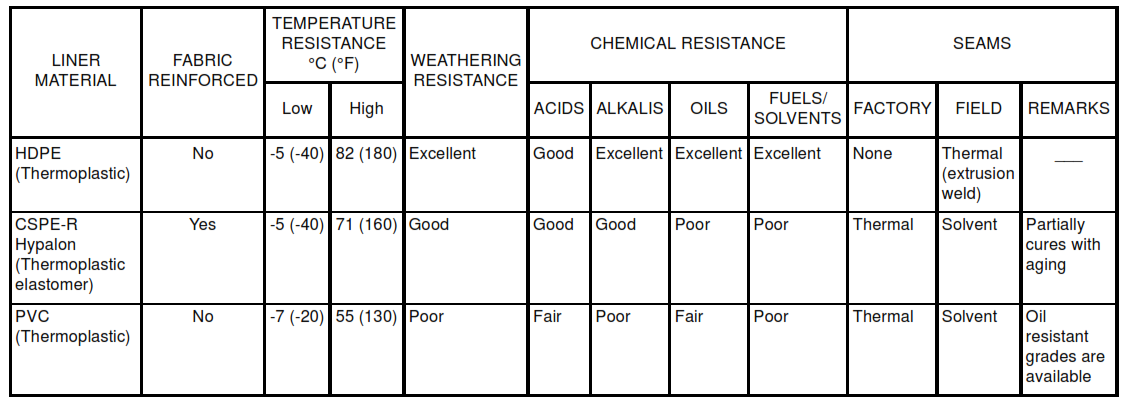
TABLE II – HDPE Resin and Extrusion Rod Properties
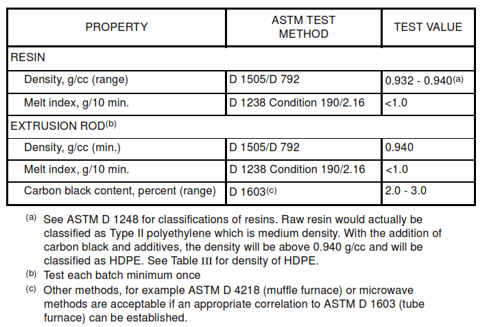
TABLE III – HDPE Liner (Smooth) Properties

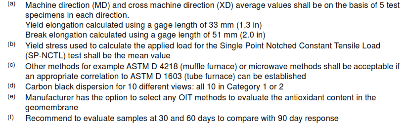
TABLE IV – CSPE-R Liner Properties
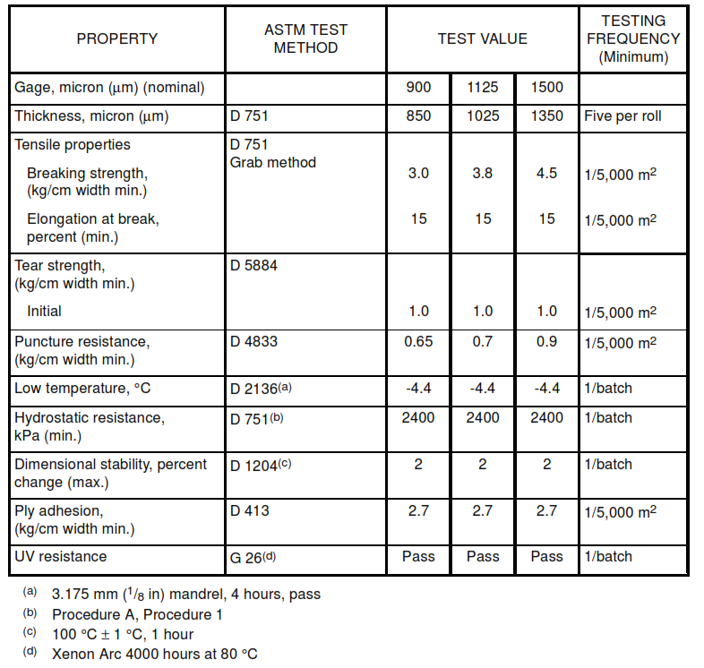
TABLE V – PVC Liner Properties