1.0 PURPOSE
2.0 SCOPE
3.0 APPLICABLE DOCUMENTS
4.0 RESPONSIBILITY
5.0 MANPOWER
6.0 TOOLS & EQUIPMENT
7.0 METHODS/PROCEDURES
8.0 QUALITY CONTROL
9.0 SAFETY PRECAUTION
10. ATTACHMENTS.
STRUCTURE & EQUIPMENT INSTALLATION OF CCR | METHOD STATEMENT
1.0 PURPOSE
This method statement shall provide minimum guidelines in accordance with project drawings and specification to installation of CCR (structure & equipment) in Plants and Refinery Projects.
2.0 SCOPE
This specification covers the minimum requirements for installation of CCR (structure & equipment) to be applied in Plants and Refinery Projects.
3.0 APPLICABLE DOCUMENTS
3.1. ARAMCO Project Specifications and Standard
3.1.1. SAEP-302 Instruction for obtaining a waiver of a mandatory Saudi ARAMCO Engineering requirement.
3.1.2. SAES-Q-005 Concrete foundation
3.1.3. SAES-Q-010 Cement Based Non-shrink Grout for Structural and
3.1.4. SAES-L-350 Equipment Grouting. Construction of Plant piping
3.1.5. SAES-H-101V – Approved Saudi Aramco Data Sheets – Paints and Coatings
3.1.6. Related Vendors Installation and maintenance manuals and /or specifications
3.2. Industry Codes Standard
3.2.1. AWS D1.1 Structural Welding Codes
3.3. Inspection and Testing Plan
3.3.1. SATIP-M-001 Structural Design for Non-Building Structure
3.3.2. SATIP-O-001-01 Typical Inspection Plan Pressure Vessel Installation
3.3.3. SATIP-Q-010-01 Cement Based Non-Shrink Grouting
3.4. Latest Revision of the following Documents shall be used
3.4.1. Vendor Drawing
3.4.2. Foundation Drawing
3.4.3. Equipment Details
3.5. Saudi ARAMCO Safety, Health and Environmental Standard
3.5.1. Construction safety manual – compliance with schedule D
4.0 RESPONSIBILITY
4.1. Construction Manager shall implement all HSE requirements for the job, shall study, analyze and schedule all construction activities with his department to include manpower and equipment line up as well as other possible resources required for the successful implementation of the construction work activities. He shall study all aspects of work procedure as per Technical Scope of Work.
4.2. Mechanical Superintendent/ Supervisor shall study and review all necessary documents for the Erection works in his area to include, technical scope of work, specification, bill of quantities, planned milestone dates and construction procedure in support to his Mechanical Foreman. He shall monitor the availability of materials in accordance with the schedules and construction analysis. He shall be directly reporting to the Construction Manager. He shall coordinate with other discipline to visualize possible conflicts in the drawings as well as in the schedules to provide other options in preventing unnecessary delays and obstructions.
4.3. Mechanical Foreman shall be responsible for the direct work supervision at site and ensured that the work is performed in accordance with Technical Scope of Work and latest approved for construction drawings. He shall monitor the availability of materials in line with his required schedule.
4.4. The Welding Supervisor and/or Foreman are solely responsible to ensure that all welding works are in conformance with applicable codes, standards, specifications and approved procedures.
4.5. QC Inspector shall be responsible in inspection and monitoring of the work and ensure that the work is performed and properly documented in accordance with Project requirements.
4.6. Safety Supervisor shall be responsible in monitoring safety aspects and ensuring that the work is done in accordance with Safety Standard Procedure. He shall discuss to the Supervisor’s the characteristics of related materials and status of work area giving reminders as an additional point to work safely.
5.0 MANPOWER
5.1. The Mechanical Supervisor shall control the overall activity. The basic manpower under him shall consist but not limited to the following:
5.1.1. Supervisor Mechanical
5.1.2. Mechanical Foreman
5.1.3. Crane Operator (ARAMCO Certified)
5.1.4. Riggers (ARAMCO Certified)
5.1.5. Welder
5.1.6. Millwright
5.1.7. Mechanical Fitter
5.1.8. Masons/Carpenters shall study all aspects of work procedure as per Technical Scope of Work.
5.1.9. Truck driver
5.1.10. QC Inspector
5.1.11. Surveyor
5.1.12. Steel Worker
5.1.13. Permit Receiver
5.1.14. Helpers
5.2. Safety Engineer/Officer
6.0 TOOLS AND EQUIPMENT
6.1. Tools and equipment needed should be in good condition and must be checked by Mechanical Supervisor/Safety Officer prior to use in the construction area. These Includes but not limited to:
6.1.1. Calibrated engineering level with calibration certificate
6.1.2. Corrective wrenches all required range
6.1.3. Certified sling and hoists
6.1 .4. Rigging accessories
6.1.5. Spreader Beam (approved by ARAMCO)
6.1.6. Welding machine
6.1.7. Concrete drill
6.1.8. Millwright Precision meter
6.1.9. Theodolite
6.1.10. Auto level
6.1.11. Crawler crane
6.1.12. Tag line nylon rope
6.1.13. Air compressor
6.1.14. Bolt tension calibrator
CCR Reactor Site Assembly Installation Procedure
7.0 METHODS/ PROCEDURE
7.1. Jobsite Receiving and Inspection
7.1.1. Upon withdrawal and receipt of equipment from warehouse, receiving inspection shall be conducted immediately as per SATI P-D-001-01 to verify compliance and latest revision of vendors drawing.
7.1.2. Record of inspection shall be documented as per SATIP-D-001-01 (Material Receiving Inspection); findings and deviations shall be documented in Quality control Inspection Report (QCIR) and Non Conformance Report (NCR).
7.2. Equipment Preservation/Protection
7.2.1. Vendor’s/Manufacturer’s recommendation for equipment preservation shall be followed: Applicable provision such (Material and Equipment Protection Program.
7.2.2. When the equipment arrived at site, shop preservation shall be checked. Where necessary damage to preservation shall be rectified without delay.
7.3. Preparatory Works
7.3.1. Secure all the valid documents prior to work commence.
7.3.2. Tools and equipment shall be made operational and available for use. Ensure tools are color-coded accordingly. Calibration certification where required shall be in valid dates.
7.3.3. Prior to the arrival of equipment on site, ARCC must be reviewed the manufacturer’s requirement and the requirements of this project specification regarding on site storage of the equipment. These requirements shall be incorporated with the preservation plan in all respects.
7.3.4. Mobilize all manpower, tools and equipment needed for the job.
7.3.5. Prepare shim if there is a requirement.
7.3.6. Install barricades to confine the area for authorized personnel only.
7.3.7. Prepare lifting location where the crane will be located and positioned.
7.3.8. Prepare and set all rigging accessories according to arrangement.
7.3.9. Checked wind condition, lift shall not proceed when wind velocity is greater than required of crane.
7.3.10. Stabilized ground areas for pre-assembly and crane location. Crane mats shall be provided in accordance to findings of soil bearing pressure.
7.4. Foundation Preparation for Vessel/ Structure
7.4.1. Confirm acceptances & turnover of civil works foundation/pedestals with a signed copy of works release notice prior to installation of Vessel / structure.
7.4.2. When the foundation released the following points shall be checked with the latest relevant drawing:
7.4.2.1 Distinct position (centre) marking and height (level) marking on the foundation, It will be referred for alignment work of level and position.
7.4.2.2 Size and number of anchor bolt and nuts, position of anchor bolts with projection.
7.4.2.3 Existence of damages and rust of threaded of buried anchor bolts with projection. Trace centerlines of foundation bolt holes with reference to gridlines. Check Verticality/plumbness of anchor bolt.
7.4.2.4 Clean the surface thoroughly by blowing with oil-free from air compressor.
7.4.2.5 Centerlines lost due to chipping operations will retrace anew Anchor bolts shall be protected properly to avoid damages during chipping/padding work and keep it up to the structure & equipment installation.
7.4.2.6 The elevation of the chipped top foundations shall allow for at least 25mm of grout under the base plate as per SAES-Q-005 Concrete foundation.
7.4.2.7 The bottom of the bases shall be cleaned and free of laitance, oil or grease.
7.4.2.8 Laitance shall be removed from the surface of the foundation and boxes by chipping to ensure good adherences of padding and grout materials to the surface preparation.
7.4.3. Dimensional Inspection and Checking of Foundation:
7.4.3.1 Using Work Transfer Sheet, following shall be done
- Establish centerlines (Northing and Easting) of columns reference to applicable foundation/civil drawings.
7.4.3.2 Confirm radius of bolts from center of equipment
- Confirm arc length in between adjacent bolts.
- Using an auto level, confirm Top of Concrete (T.O.C.) elevation.
7.4.3.3 Compare data with reference drawings and Survey Data Record. Note the discrepancies and unacceptable tolerances and report through QCIR.
7.4.4. Padding
7.4.4.1 Pads and liners shall be machined flat parallel and larger than the foot of base frame.
7.4.4.2 Pads material shall be in accordance with ASTM A283 Gr. C,D or equivalent.
7.4.4.3 Pad shall be hot dip galvanized in accordance with ASTM A123 or coated with zinc rich epoxy primer in APCS-1C of SAES-H-101 as applicable
7.4.4.4 In general, the distance between pads shall not exceed 800mm. If the distance becomes more than 800mm, an additional pad shall be added in between.
7.4.4.5 Pad size shall be selected as per the anchor bolt size as follows:
- Bolt diameter M24 or 1 inch and below Pad width 50mm
- Bolt diameter M30-M48 or 1-1/4 to 2 inches Pad width 75mm
- Bolts diameter M56 or 2-1/4 inches and above Pad width 100mm
7.4.4.6 Number of pads shall be determined so the load pressure will be less than 30kg/cm2 as per following formula. The supporting load can be calculated
L=W/NxAxB
L: Load supported by pad (kg/cm2) W: Lifting load of equipment (kg)
N: Number of pads
A: Width of pad plate (cm)

7.4.4.7 The length of pad shall be 20 mm to 30 mm longer than the width of the equipment bases.
7.4.4.8 The thickness of the both taper and straight liners shall be at least 10 mm and the minimum thickness of the tapered ends shall be 2 mm. Adjustment allowance shall be 4 to 6 mm.
7.4.4.9 The wedge liners may be applied to tower and vertical vessel, If necessary. The gradient of the wedge liners shall be generally less than 1/30, and two wedge liners shall be used in back to back so as to make their top and bottom faces in parallel.
7.4.4.10 After finishing padding work, following points shall be checked.
- Position of center and elevation line of foundation
- Elevation and position of pads
- Cleanliness of concrete surface
- Condition of anchor bolts
7.5. Erection of CCR (equipment & structure)
7.5.1. Prepare lifting location where the crane will be located and positioned.
7.5.2. Prepare and set all rigging accessories according to arrangement.
7.5.3. Checked wind condition, lift shall not proceed when wind velocity is greater than required of crane.
7.5.4. Stabilized ground areas where crane will be located and positioned. Crane mats shall be provided in accordance to findings of soil bearing pressure.
7.5.5. Rigging plans to use shall be approved by clients.
7.5.6. Using required crane, pre-assemble equipment steel structure of CCR (first lift). After completion of pre-assembly erection shall commence. Align and plumb structure as per SATIP-M-001 prior for erection of equipment.

7.5.7. Erection of equipments such as Reformer feed /effluent exchanger, 1 upper hopper fines filter and upper surge drum fines filter.

7.5.8. Erection of 2″ lifts equipments steel structure.

7.5.9. Erect ring saddle of Reactor prior to erection of J10-C-0404.
7.5.10. Set saddle ring on correct orientation, center-line of saddle ring and J10-
C-0404 must be at the same orientation. Adjustment of reactor elevation
will be done using shim plates. Follow welding sequence (attachment 2) to
prevent support ring beam on distortion.


See attachment 2 for welding sequence between ring support and beam structure.
7.5.11. After full welding of ring saddle support touch-up paint on all damaged paint as per S-100-13A0-00 1.
7.5.12. Commence Erection of 4″ reactor upon attaining the required orientation and elevation, followed by 3″ reactor, 2″ reactor, 1 reactor, oxychlorination heater, calcinations heater and regenerator.
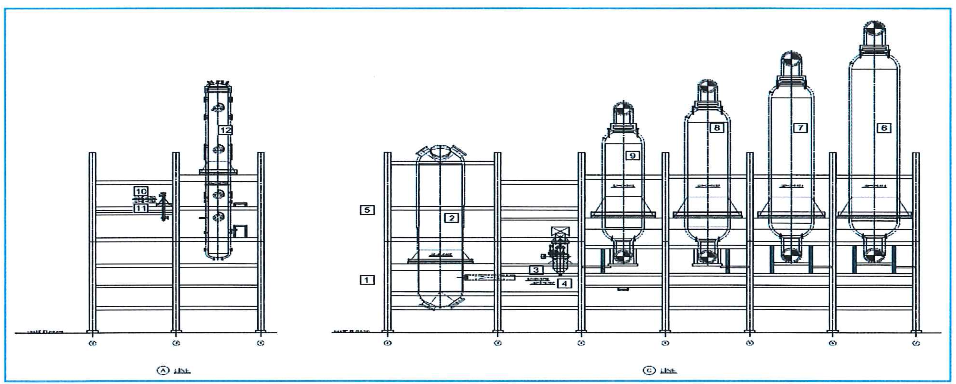
7.5.13. Erection of 3″ lifts equipments steel structure.
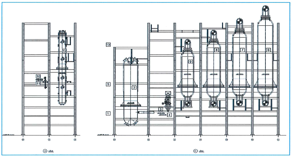
7.5.14. Erections of hydrogen lift gas exchanger, reduction exchanger and burning heater.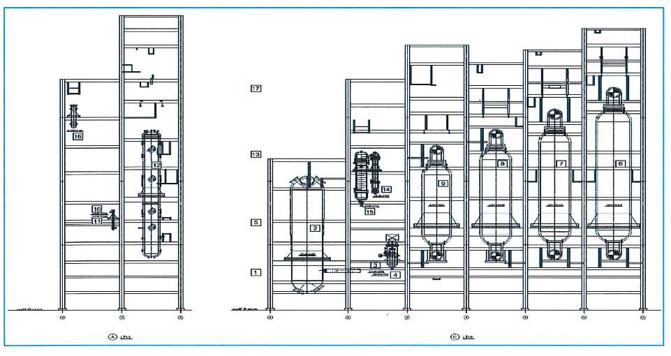
7.5.15. Erection of 4″ lifts equipments steel structure.
7 .5.16. Erections of reduction heater, burning feed/effluent exchanger, reduction chamber, 2″ upper hopper, calcinations feed/effluent exchanger, lock hopper, 3″ upper hopper, 1 upper hopper, 1° balance drum, 4″ upper hopper, 2″ balance drum, upper surge drum and 3rd balance drum.
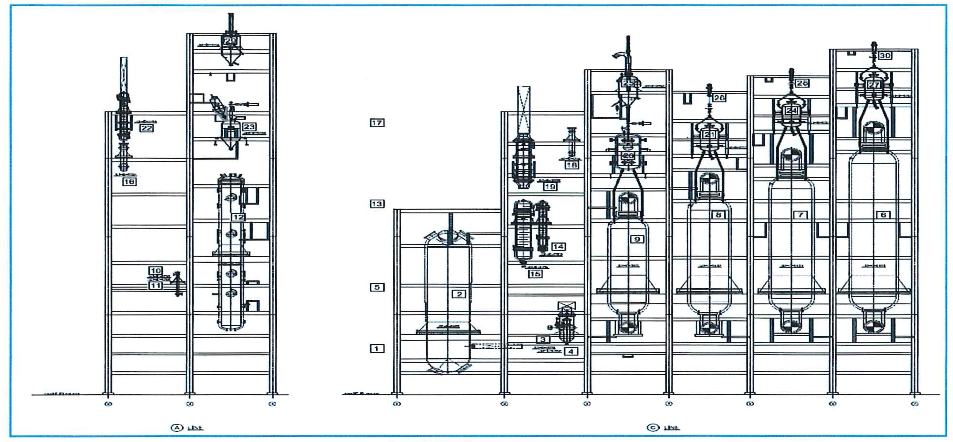
7.5.17. Erections of 5″ lower hopper, 5″ lift pot, 4″ lower hopper, 4″ lift pot, 3″° lower hopper, 3″ lift pot, 2″ lower hopper, 2″ lift pot, 1 lower hopper, 1″ lift pot.

7.5.17. Erections of 5″ lower hopper, 5″ lift pot, 4″ lower hopper, 4″ lift pot, 3″° lower hopper, 3″ lift pot, 2″ lower hopper, 2″ lift pot, 1 lower hopper, 1″ lift pot.
7.5.18. Erected structure and equipments will be inspected by SAUDI ARAMCO after alignment.
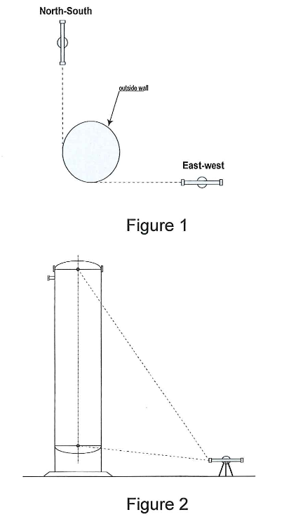
7.6. Plumbness check (See Figure 1-3)
7.6.1. Take sight on the reference point at the top.
7.6.2. Close the horizontal adjustment knob to lock line of sight of equipment against horizontal movement.
7.6.3. Take sight on the reference point on the bottom.
7.6.4. Out-of-plumb dimension from the reference point at the bottom can be measured from the reference point to the survey instrument line off sight using steel tape/measuring stick.

7.6.5. Use carbon steel shims if needed to adjust verticality and plumbness. Wedge blocks when nosed during adjustments shall be removed after alignment.
7.6.6. Shims used for level alignment shall be:
7.6.6.1 Less than 0.0110°(2.5 mm) thick shall be stainless steel.
7.6.6.2 Shim thicker than 0.100(2.5 mm) shall be carbon steel.
7.7. Setting and Alignment
7.7.1. The alignment of tower vessels of which the height is more than 20 m should be checked before dawn or in cloudy days.
7.7.2. Vessel shall be aligned at the proper position, elevation and levelness within the Tolerances specified in Para 7.11.
7.7.3. Check elevation, levelness, squareness and plumbness as per SATIP-D-001-01 Typical Inspection Plan Pressure Vessel Installation.
7.7.4. After any installation of the equipment and up to grouting commencement foundation Chipped surface shall be protected from harmful contamination for grouting with a Suitable way.
7.8. Bolt Tightening
7.8.1. All bolts shall be aligned to permit insertion of bolts without undue damage to the threads.
7.8.2. Bolts shall be placed in all holes with washers positioned and nuts threaded to complete the assembly.
7.8.3. Any abnormal wear on the equipment and parts during installation ad assembly shall be corrected. Prior to the commencement action written work procedure shall be approve by contractor/company.
7.9. Grouting
7.9.1. Water for mixing grout non-shrink material must be fresh and clean, and free from Injurious of oil acid alkali, salt or organic as per SAES-Q-010 Cement Based, Non- Shrink Grout for structural and Equipment Grouting.
7.9.2. This grout shall meet the requirement of STS 03600 when used in high fluidity range. Compressive strength shall be in excess of 34.5 Mpa (5000 psi) when mixed according to manufacturer instructions.
7.9.3. Grout shall be mixed in accordance’s with grout manufacture’s instruction. Contractor Shall prepare sufficient quality of grouting material, clean tools and equipment and suitable water mixture at site to complete the job.
7.10. Setting of liner
7.10.1. Prior to the installation of liners and equipment, the liners and grouting portion of foundation shall be chipped and all concrete laitance shall be removed from portion.
7.10.2. Flat liners shall be installed at the positions as described in Para 7.6 with pads of cement grout at least seven days before equipment installation. lncase non-shrink grout material is used; the curing duration shall according to the manufacture’s recommended.
7.10.3. In case that wedges liners are used the level of padding with a flat liners need to be adjust to meet with the final equipment elevation.
7.11. Alignment Tolerances
7 .11. 1 . Position ±3mm
7.11.1.1 Every 90 degree orientation of base plate shall be measured with reference to the Orientation of the foundation
7.11.2. Elevation ±3mm
7.11.2.1 The bottom of base plate shall measure with reference to the level marking of the foundation. At least, one point of the base plate shall be aligned within these tolerances.
7.11.3. Levelness 1/1,000 (for horizontal equipment)
7.11.3.1 The center line of equipment shall be in alignment with the horizontal line within the tolerances of 1/1,000. If slope is required, the inclination shall be considered
7 .11.4. Perpendicular ±6mm for each 1 Om (for vertical equipment only)
7.11.4.1 The center line of the equipment shall be in alignment with vertical line within the tolerance of ±6mm for every 10m length of the equipment, in principle, provides that such tolerance 20m and longer equipment shall not exceed ±12mm.
7.11.5. Damages and Nonconformity
7.11.5.1 Any damages and defects and nonconformity found at site and lay down yard shall be reported immediately.
8.0 QUALITY CONTROL
- QC personnel shall be assigned to ensure the quality control and assurance requirement of the project.
- QC Inspector shall coordinate with other inspector to conduct inspection as required in SATIP.
- QC Inspector shall be responsible to conduct all required inspections/documentations and to ensure that all applicable requirements, codes, and standards are complied with.
- Contractor has to utilize the applicable SAIC for every activity.
- Calibration shall be done as required for all machines and tools going to be used in the work in accordance with schedule Q.
9.0 SAFETY PRECAUTION
Obtain the approval of the work permit from the concerned Representative before starting any work.
9.1. Fire Watcher with Fire Extinguisher shall be at work area whenever there is hot work.
9.2. All electrical tools shall be checked and color-coded.
9.3. Continuous monitoring and inspection shall be done by Mechanical Supervisor and Safety Supervisor and it shall be continuously implemented to detect and correct unsafe practices while performing the work activities.
9.4. Provide warning sign and sufficient barricade on working area and only assigned personnel will be allowed in the area.
9.5. Safety harness with double lanyards shall be used all the time when working at elevated temporary platforms 1.8 meters high and above.
9.6. Man lift users shall be trained and certified to operate and use the equipment.
9.7. Mechanical Supervisor shall monitor the work activities to help and to protect all assigned workers against exposure to safety hazards. He shall ensure that Personal Protective Equipment (PPE’s) are supplied and used and comply with applicable standards. HSE will assist in giving advice.
9.8. All rigging equipment shall be in good condition and possess a valid certification from authorized certifying and inspection department inspection and color coding shall be done in accordance will inspection guideline.
9.9. Toolbox meeting shall be conducted by Mechanical Supervisor daily so as work activities will be properly coordinated to all concerned and all safety infractions will be acted on immediately.
9.10. All necessary personal protective equipment (PPE) shall be provided and to be worn at all times.
9.11. Housekeeping shall be maintained and working area shall be kept in a clean and tidy manner.
9.12. Job Hazard and Risk Assessment (JHRA) of this method statement shall be disseminated and explained to workers prior to start of work.
10.0 ATTACHMENT
Job Hazard and Risk Assessment (JHRA)
Welding Sequence