This article is about Thermocouples (Including Extension Wire) Material Selection Criteria & Design, Installation Techniques, Technical specification of thermocouple and Checklist For Temperature Measurement of Instrumentation and Control Systems as per International Codes and standards for Commercial Buildings, Plants and Refinery Projects.
Thermocouples (Including Extension Wire) Material Selection Criteria & Design
Material Receiving General Checklist for Instrumentation & Control
Purchase Order and Instrument specification sheet criteria shall be confirmed and compared with instrument stainless steel tags / labels and nameplates, and shipment checked for damage, prior to acceptance of the shipment.
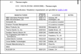
Verify that all the instruments are from technically acceptable manufacturer.
Thermocouple selection shall be determined by the temperature range to be measured. Type E, Type J, and Type K thermocouples are typically used in Plant and Refinery facilities.
Commentary Note: Type J TCs contain iron wire which is subject to corrosion in many locations. See attachment 2, table 1 for temperature range
Thermocouples and extension wires shall meet the requirements as detailed in table 1-6 (attachments 2 & 3 ) to establish uniformity in the designation of thermocouples and extension wires and to provide, by means of the color of its insulation, an identification of its type or composition as well as its polarity when used as part of a thermocouple system. [ISA-MC96.1-1982 Sec.1]
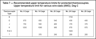
The wire sizes normally used for non-sheathed thermocouples shall meet the following requirements:
For J, K, and E: 8, 14, 20, 24, and 28 AWG*
For T: 14, 20, 24, and 28 AWG*
For R, S and B: 24 AWG* only[ ISA-MC96.1-1982 Sec. 2.3.1]”
Extension wires shall comply with the following: The wire sizes normally used for extension wire, either singly or in pairs, are 14, 16, and 20 AWG*. Sixteen (16) gage is most commonly used. Twenty (20) gage and smaller may be used when bundled and reinforced to provide strength for pulling. These sizes apply to all types of extension wires. [ISA-MC96.1-1982 Sec. 2.3.2].
Electrical and electronic installation and wiring of temperature instrumentation shall be in compliance with SAES-J-902.
Exception: Cast Aluminum heads may be used.”
All thermocouple instruments/ devices shall provide burnout detection. The direction of the readout or output signal on thermocouple burnout shall be selectable.
Thermocouple transmitters shall provide input and output signal isolation, cold junction compensation, linearization/ characterization, ambient temperature compensation, and adjustable damping.
Temperature transmitters shall meet the NEC hazardous area classification of the intended installation. Transmitters certified as nonincendive are preferred in order to eliminate sealing the device in Class I, Div. 2 hazardous areas.
Transmitters with smart electronics are required since they provide enhanced output accuracy and rangeability, as well as remote calibration and diagnostic capabilities.
Thermocouple switches shall meet the NEC hazardous area requirements of the intended installation.
Electric switch contacts shall be snap-acting, single-pole, double-throw (SPDT), 5 amps at 120 VAC resistive, as a minimum. The switch mechanism shall be user-selectable to activate on increasing or decreasing temperature.
The switch shall provide cold junction compensation..
Multipoint temperature indicators shall consist of a panel-mounted readout and a means of selecting the desired thermocouple to display.
Multiplexers shall take the signals from a number of thermocouples as inputs and provide an output to a logic control system (DCS, PLC, etc.).
Multipoint indicators and multiplexers shall provide linearization, cold junction compensation and scaling of the thermocouple input signals.
A maximum of 100 thermocouple inputs (including spares) shall be permitted per multipoint indicator or multiplexer. Recommended spare capacity is 25% of the number of occupied inputs.
Outer Jacket Marking
The following information shall be clearly marked on the outer jacket of the cable, in no specific order:
a) Manufacturer’s name, trade name, catalog or type number
b) Number of pairs/triads
c) Conductor size in mm² or AWG
d) Voltage rating (300 or 600 V)
e) Type of cable (PLTC, TC or equivalent)
f) Approval mark of listing authority (UL, IEC, BS, DIN, or equivalent)
g) “”Sunlight resistant”” designation, in Manufacturer’s standard nomenclature, for Type TC cable (Optional for Type PLTC cable)
h) “”Direct burial”” designation, if applicable per UL 13 or UL 1277, in Manufacturer’s standard nomenclature
i) “”Oil resistant”” designation, in manufacturer’s standard nomenclature, for Type TC Cable (preferred for Types ITC and PLTC Cable) [34-SAMSS-913, Sec 7.1]
International Codes and Standards for Thermocouples (Including Extension Wire) Material Selection
- Flow Nozzle Material Selection Criteria Design & Flow Measurement
- Venturi Tube Material Selection Criteria Design & Flow Measurement
- SAES-J-002 – Technically Acceptable Instruments Manufacturers, 23 June 2008.
- SAES-J-003 – Instrumentation – Basic Design Criteria, 16 January, 2008
- SAES-A-112 – Meteorological and Seismic Design Data, 31 October 2006
- SAES-J-400 – Temperature, 31 May 2004
- SAES-J-902 – Electrical Systems for Instrumentation, 11 May, 2008
- ISA / ANSI/ MC96.1 – Temperature Measurement Thermocouples-1982
- STD. DWG. AB-036019 Thermowell Assembly and detail rev 21
- 34-SAMSS- 913 – Instrumentation and Thermocouple Cable.ATTACHMENTS:
1. Attachment 1: SAES-A-112 Sec. 4.6 Ambient Air Quality
2. Attachment 2: ISA-MC96.1-1982 Sec. 1 Coding of Thermocouple Wire and Extension Wires


3. Attachment 3: Color Coding of Thermocouple Wire


