This article is about Flow Nozzle Material Selection Criteria Design for Flow Measurement of Instrumentation and Control Systems as per International Codes and standards for Commercial Buildings, Plants and Refinery Projects.
Flow Nozzle Material Selection Criteria Design – Flow Measurement
Material Receiving General Checklist for Instrumentation & Control
General Requirements
Purchase Order and Instrument specification sheet criteria shall be confirmed and compared with instrument stainless steel tags / labels and nameplates, and shipment checked for damage, prior to acceptance of the shipment
Verify that all the instruments are from technically acceptable vendors (Attachment 1)
Flow nozzle shall be designed to bolt between flanges unless otherwise required by service application and piping specifications. See Attachment “2 & 3” (PIP PCCFL001 Sec. 3.3.1)
In high pressure (1000 psig or higher) applications, the flow nozzle shall be welded directly into the pipe. (PIP PCCFL001 Sec. 3.3.2)
Tap connections shall be installed 1 inside pipe diameter upstream and 1/2 inside pipe diameter downstream in accordance with ASME-MFC-3M. (PIP PCCFL001 Sec. 3.3.3)
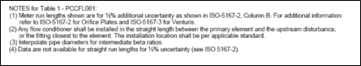
“Minimum straight run pipe length requirements shall be in accordance with Table 3 (Attachment 4)
Comment: Where owner approves additional metering uncertainty,
minimum piping run lengths may be in accordance with ASME-MFC-3M. (PIP PCCFL001 Sec. 3.3.4)”
Flow nozzles shall be 316 SS unless otherwise required by process service or piping specifications. (PIP PCCFL001 Sec. 3.3.5)
International Standard and Codes for Instrumentation Accessories
- Turbine Meter Material Selection Criteria Design & Flow Measurement
- Pitot Tube Design Requirement in Process Industry
3. SAES-J-002 -Technically Acceptable Instruments, 23 June 2008
4. SAES-J-003 – Instrumentation Basic Design, 16 January 2008
5. SAES-J-100 – Process Flow Metering, 05 April 2008
6. PIP PCCFL 001 – Flow Measurement Criteria , August 2006, Process Industry Practices Process Control,
7. API 14.3.2 Part 2 – Manual of Petroleum Measurement Standards Chapter 14 – Natural Gas Fluids Measurements
1. Attachment 1: Technically Acceptable Instruments, SAES-J-002.

2. Attachment 2: Minimum Straight Run Lengths for Orifice Runs and other Flow Elements, Per ISO 5167-2, Column B, PIP PCCFL001.

3. Attachment 3: Minimum Straight Run Lengths for Orifice Runs, Per ANSI/API (ISO 5167-2, Column A), PIP PCCFL001.
, PIP PCCFL001")
, PIP PCCFL001")
4. Attachment 4: Minimum Straight Run Lengths for Venturi Tubes and Flow Nozzles, Per ANSI/API (ISO 5167-3) PIP PCCFL001.
 PIP PCCFL001.")