This article is about Turbine Meter Material Selection Criteria Design – Flow Measurement of Instrumentation and Control Systems as per International Codes and standards for Commercial Buildings, Plants and Refinery Projects.
Turbine Meter Material Selection Criteria Design – Flow Measurement
Material Receiving General Checklist for Instrumentation & Control
General Requirements
- For high-accuracy applications, liquid turbine meters shall be installed in accordance with API MPMS, Chapters 5 and 6. (PIP PCCFL 001 Sec. 3.7.7; API MPMS Chapter 5 and 6)”
- For all applications, each turbine meter and its accessories shall meet the requirements set forth in API MPMS 5.3 and API MPMS 5.4. (34-SAMSS-117 Sec. 7.2.1; PIP PCCFL001 Sec. 3.7.9)
- The Vendor shall implement and maintain a Quality Program which shall include clearly defined and documented procedures for the relevant Quality System functions. The Quality Program documents shall be made available to the Buyer Representative for review and audit. (34-SAMSS-117 Sec. 8.1; PIP PCCFL001 Sec. 3.7.9)
- “Meter shall be tested in accordance with API MPMS 5.3, Appendix C to ensure that it meets the requirements for linearity (and flow rate turndown) and repeatability as specified for the application in Section 7.7. (see below). [34-SAMSS-117,Sec. 10.1.2 and 7.7; PIP PCCFL001 Sec. 3.7.9]

Storage, Handling, and Preservation
The manufacturer’s storage, handling and preservation instructions to be followed.
Material Requirements
- Purchase Order and Instrument specification sheet criteria shall be confirmed and compared with instrument stainless steel tags / labels and nameplates, and shipment checked for damage, prior to acceptance of the shipment
- Verify that all the instruments are from technically acceptable vendors
- All turbine meters and their installations shall comply with 34 SAMSS-117 (PIP PCCFL001 Sec. 3.7.9).
- Viscosity compensated turbine meters shall not be used (PIP PCCFL001 Sec. 3.7.8).
- The following information shall be stamped/embossed on the stainless steel tag permanently attached to the meter body:
● Manufacturer
● Part/Model No.
● Serial No.
● Instrument Tag No.
● Nominal Size
● ANSI Class (Flange Rating)
● Capacity Data
● K-Factor
● Material of Construction [34-SAMSS-117, Sec 9.1; PIP PCCFL001 Sec.3.7.9] - Flow direction shall be indicated by an arrow on the meter body and/or by the words IN and OUT on the piping connections. (34-SAMSS-117, Sec 9.2; PIP PCCFL001 Sec. 3.7.9)
- The turbine meter and associated accessories shall operate continuously under the following ambient air temperatures and humidity without any degradation of the manufacturer’s guaranteed performance: ( 34-SAMSS-117,Sec. 5.2.1.1; PIP PCCFL001 Sec. 3.7.9)

- Offshore and Nearshore Environment (If specified by the Saudi Aramco Form 8020-117-ENG)
Equipment which is not enclosed or hermetically sealed, but is situated offshore or nearshore, shall be protected against corrosion and operational failure due to wind-borne sea water spray and the accumulation of wetted salt (NaCl). Nearshore is defined as any outdoor, onshore location within one kilometer from the shoreline of the Arabian Gulf; all of the Ras Tanura Refinery and Terminal; and within three kilometers from the shoreline of the Red Sea. [34-SAMSS-117,Sec. 5.2.2; PIP PCCFL001 Sec. 3.7.9] - Enclosures:
The instrument manufacturer shall ensure that all equipment installed outdoors is designed to withstand the environmental conditions.
All enclosures shall be water and dust-tight in accordance with NEMA ICS 6 and NEMA 250 Type 4X or IEC 60529 Type IP65, and suitable for the electrical area classification. [34-SAMSS-117,Sec. 5.2]” - Area Classification:
Electrical equipment or devices which may produce arcs, sparks or high
temperatures, and which are intended for operation in locations classified under NFPA 70, National Electrical Code (NEC) Article 505, shall be listed or labeled by any of the following authorities: [34-SAMSS 117,Sec. 6.1]”

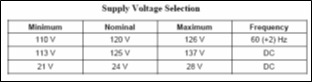
Main Power Sources:
- Main electrical power sources for instruments may vary within the limits shown in below, unless specified otherwise on the ISS. [34-SAMSS-117,Sec. 6.2]”

“Each turbine meter shall be furnished with two magnetic pickup coils mounted so as to produce signals that are 90 degrees out-of-phase. Each pick-up coil shall be provided with a preamplifier. [34-SAMSS-117, Sec 7.6.1.1]”- Each pick-up coil and pre-amplifier shall be located in an enclosure that is designed or positioned to eliminate the potential for accumulation of condensation. [34-SAMSS-117, Sec 7.6.1.2]
- The output of the magnetic pickup preamplifier shall be a 0-12 Volt square wave signal. [34-SAMSS-117, Sec 7.6.2.3]
- The turbine meter shall have desiccant included and shall be air-tightly wrapped in shrink-wrap or equivalent. [34-SAMSS-117, Sec 8.3]
- In-line type turbine meters 1 inch (25 mm) and above shall be flanged. (PIP PCCFL001 Sec. 3.7.4)
International Standard and Codes for Turbine Meter Material
- Pitot Tube Design Requirement in Process Industry
- General Instrumentation Accessories Installation Design Notes
3. SAES-J-003 – Instrumentation Basic Design, 16 January 2008
4. SAES-J-100 – Process Flow Metering, 5 April 2008
5. PIP PCCFL 001 – Flow Measurement Criteria , August 2006, Process Industry Practices Process Control,
“6. API MPMS – Manual of Petroleum Measurement Standards, Chapter 5, Metering, Section1, General considerations for Measurement
by Meters, Third Edition, September 1995.”
“7. API MPMS – Manual of Petroleum Measurement Standards, Chapter 6, Metering Assemblies, Section 7, Metering Viscous
Hydrocarbons, second Edition, May 1991”
8. 34-SAMSS-117 – Turbine Flow meters in Liquid Service, 29 July 2007