This article is one of the Flow Measurement articles. It addresses Venturi Tubes and Flow Tubes and discusses their application, suitability, calculation, working principle, venturi tube diagram, equation, types, advantages, and disadvantages compared to the more common orifice plate metering method. Also listed are precautions to be observed in their application.
What is Venturi Tube?
A Venturi tube is an instrument used to measure fluid flow in a pipe. It consists of a tube with a narrowing throat section in the middle. When fluid flows through the Venturi tube, its velocity increases as it passes through the narrower section, causing a pressure drop. This pressure drop is measured using pressure sensors placed before and after the throat section.
The principle behind the Venturi tube is based on Bernoulli’s principle, which states that an increase in the speed of a fluid occurs simultaneously with a decrease in pressure or a decrease in the fluid’s potential energy.
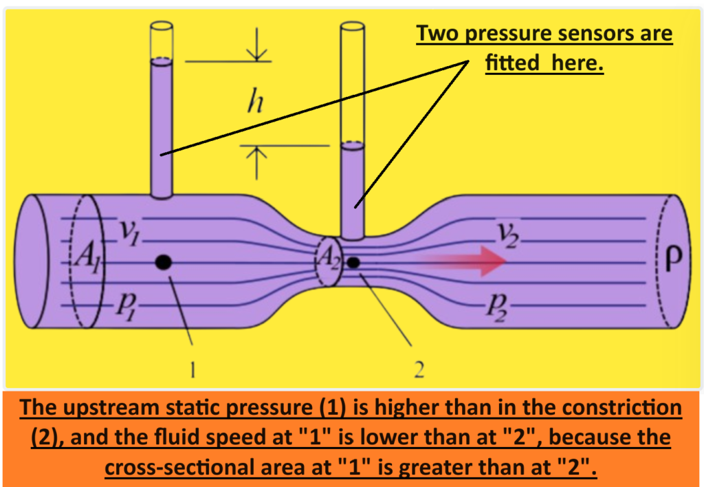
By measuring the pressure difference between the two points in the Venturi tube, the flow rate of the fluid can be calculated using equations derived from Bernoulli’s principle. Venturi tubes are commonly used in various industries, including water supply systems, chemical processing plants, and plant instrumentation systems, to accurately measure fluid flow rates.
References.
Reference is made in this standard to the following documents.
American Society of Mechanical Engineers (ASME): Fluid Meters, Their Theory and Application.
Venturi Tube Design Requirements.
The Venturi Tube is a head (differential pressure) producing primary flow element intended for use with indicating, transmitting, totalizing, or combinations of secondary instruments accepting differential pressure input. A measure of the differential pressure created in the venturi tube is a measure of flow rate.
The Venturi Tube (Figure 1) Consists of:
- Converging conical inlet section in which the cross section of the stream decreases and the velocity increases with consequent increase of velocity head and decrease of pressure head.
- Cylindrical throat which provides for a point of measurement of the decreased pressure in an area where flow rate is constant.
- Diverging recovery cone in which velocity decreases and the decreased velocity head is recovered as pressure.
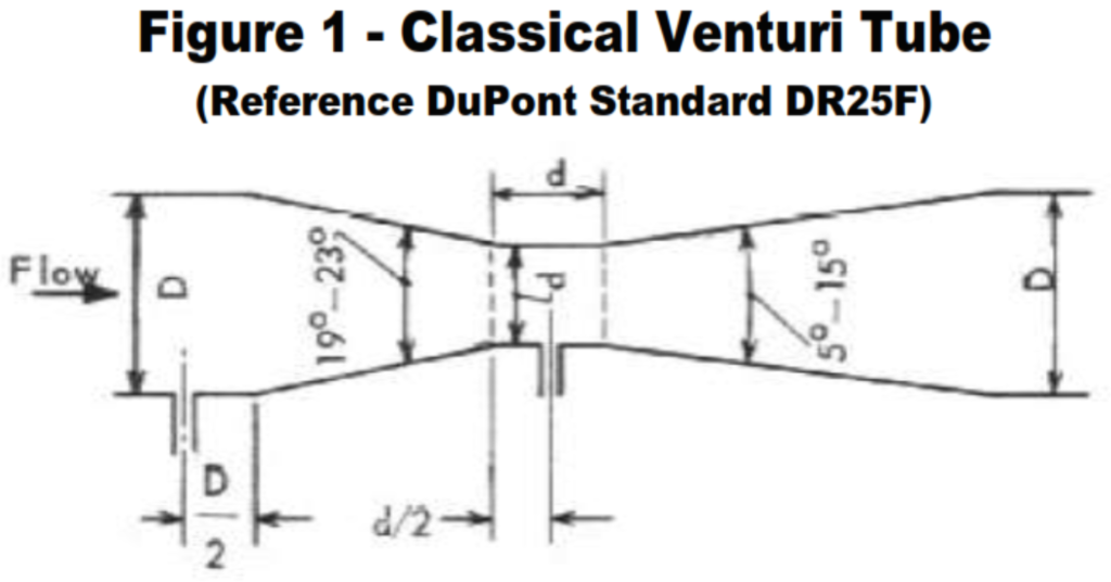
The differential pressure measurement taps are located one-half pipe diameter upstream of the inlet cone and at the middle of the throat. Sometimes piezometer rings are used in place of simple pressure taps. A ring consists of several openings in the inner wall of the tube in a plane perpendicular to the axis of the venturi. The holes are interconnected to provide an average pressure.
There are several proprietary primary head-type devices which have a higher ratio of pressure developed to pressure loss than the venturi tube. They are considerably more compact than the classical venturi tube with its long recovery cone. Devices of this type commonly are used in large liquid flow applications.
- There are four typical units available which include the Gentile Patent Flow tube, the Dall tube, the Lo-Loss tube, and the Twin-Throat venturi tube. These are proprietary devices with a combination of contour and tap locations designed to give a high differential pressure with a low permanent pressure loss. They vary in the contour used but all are less than four diameters long. The relationship between flow and differential pressure is similar to that of other head-producing primary elements.
- Manufacturers of these proprietary designs provide Reynolds number versus flow-coefficient data. The devices are subject to flow-coefficient change with viscosity variation. In general, these devices are not recommended for sticky liquids since any accumulation may affect the flow coefficient seriously. None has the smooth contour of the venturi tube.
- These devices are available in medium to very large sizes. There is little justification for their use in small flow, small pipe applications. In the large sizes, the installed cost generally is less than that for the classical venturi tube with its long recovery cone for maximum pressure recovery.
- Accuracy depends upon the accuracy of the manufacturer’s calibration data. Actual flow calibration, particularly for the larger sizes, can be difficult and expensive.
- Derivation of flow coefficient by extrapolation from theory and test data on smaller sizes is much less direct than for the simply structured venturi tube.
- The extensive tests under a wide range of conditions which support orifice meters do not exist for these proprietary devices.
Applications.
Venturi tubes are used for measuring small process streams less than one gallon per minute, to very large flow rates limited only by the pipe size. Sizes usually range from ½ inch to 48 inches although larger sizes have been built and are available.
Theory, general performance, and calculations for the venturi tube are similar to those for the orifice plate and flow nozzle. Following are some of the similarities and dissimilarities of these three primary elements.
- Due to its length and machining requirements, the venturi is the highest-cost element. The flow nozzle is lower in cost with the orifice plate the least expensive.
- In contrast to the orifice and nozzle, the venturi requires no straight downstream piping, except a straight run of two pipe diameters before a valve. Requirements for upstream piping are similar to that for the orifice and nozzle.
- One manufacturer (BIF) offers a Universal venturi with a hydraulic design between the inlet and throat that conditions the velocity profile at the throat tap, virtually eliminating all upstream piping effects. Tests with a 2-inch element with 0.45 beta ratio showed no appreciable effect with a throttled gate valve and a 90-degree elbow four pipe diameters upstream.
- Flow coefficient increases up to a certain point with increase of Reynolds number for the venturi and nozzle and decreases for the orifice plate.
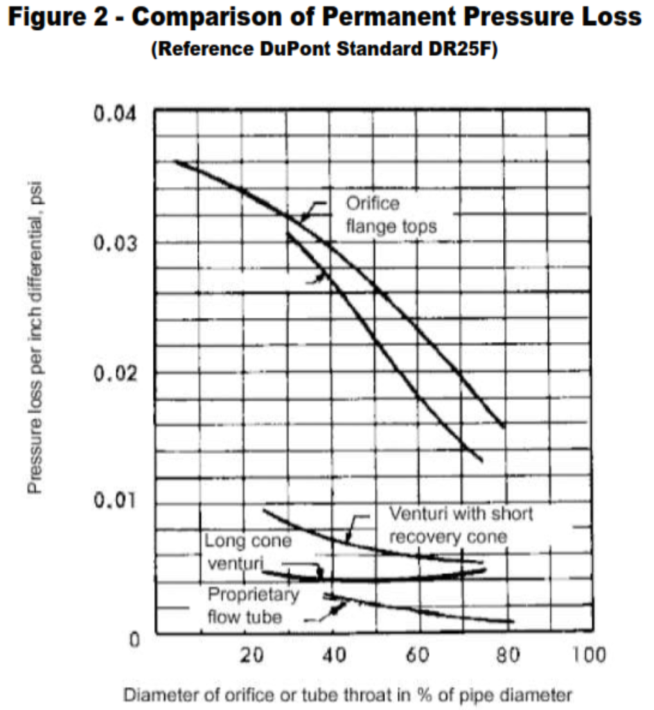
- The permanent pressure loss is highest in the orifice, slightly lower in the nozzle, and considerably lower in the venturi. See Figure 2.
- Since the flow rate is proportional to the square root of the pressure drop for all three elements, their calibration curves are nonlinear and the useful measurement range is limited to about 3 to 1 turndown. Pressure drop increases rapidly with flow rate increase.
The venturi tube has no sudden changes in contour, no sharp corners, and no projections into the fluid stream. Because of this, it may be used for measurement of dirty fluids, slurries, sludge, and gases with entrained liquids or solids such as monomers and polymers which tend to build up on or plug other primary devices. However, protecting the pressure taps from plugging can be a real problem.
Types of Venturi Tubes used in Industry.
- Eccentric Venturi Tube.
- Rectangular Venturi Tube.
The venturi tube sometimes is modified to an eccentric configuration (Figure 3) with the bottom of the throat in the same horizontal plane as the bottom of the connecting pipe.
This provides further assurance that buildup of heavy materials will not occur and also permits complete draining of horizontal lines.
Rectangular Venturi Tube.

- Pumping costs or process requirements may indicate consideration of the venturi because of its low permanent pressure loss.
Venturi Tube Advantages
- Permanent pressure loss is very low due to the smooth gradual profile of the recovery cone.
- Because of the low permanent pressure loss, substantial power savings may be realized where large quantities of fluid are metered.
- Has no sudden changes in contour, no sharp corners, and no projections into the fluid stream to interfere with the passage of undissolved or entrained materials.
- Because of the smooth gradual profile, resists wear due to abrasion.
- Suitable for high-velocity applications.
- Will develop sufficient differential pressure for reliable flow measurement on much lower static pressure applications than will orifice plates or flow nozzles.
- Provides the lowest noise level of any of the differential-pressure producing primary elements.
- Less affected than orifice plates and flow nozzles by pipeline configurations.
- The discharge coefficient is less affected by Reynolds number than either a nozzle or an orifice and therefore more accurate over a wider flow range.
Venturi Tube Disadvantages.
- Since the flow rate is proportional to the square root of the pressure drop, the calibration curve is quadratic, limiting measuring range to about 3 to 1.
- Flow calculations based upon dimensions are less reliable than those for orifice plates.
- Limited available data for low Reynolds number, small sizes, or contours other than classical.
- Manufacturing and handling costs are high.
- Awkward to handle due to size and weight. Inspection in place is difficult.
- Modifying an existing venturi to increase capacity is difficult and impractical.
- Not easily fabricated or modified on the plant.
- Changes in the friction effect due to corrosion or erosion may be substantial because of the considerable contact area between the flowing fluid and the inlet cone.
Venturi Tube Precautions.
- Accuracy is dependent upon correct fabrication and installation.
- Flow calibration is recommended where high accuracy is required.
- The inside surface finish of the venturi can have a significant effect upon the flow coefficient.
- Piezometer connections are unsuitable for use with purge systems employed for slurries and dirty fluids.
- Proprietary devices that deviate from the classic venturi design are highly subject to flow coefficient changes with changing fluid parameters.
- For greater accuracy, diameter ratio (beta ratio) ? shall be 0.3 < ? < 0.75.
Venturi Tube Calculations.
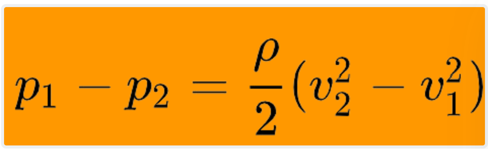
For convenience, the following equations are included for venturi tube calculation. They are based upon ASME “Fluid Meters”.
Working equations: (Reference DuPont Standard DR25F).
If (P1 – P2)/P < 0.01, y > 0.99
where
P1 1 = Inlet pressure psia.
P2 = Throat pressure, psia.
ß = Ratio of throat diameter to inlet pipe diameter.
µ = Viscosity, flowing, centipoise.
Ρ = Density, inlet, pound per cubic foot.