- SCOPE
- REFERENCES
- GENERAL
- SAFETY
- EXECUTION
5.1 Joint Preparation
5.2 Precautions
5.3 Welding Steel Backing
5.4 Back-Gouging or Grinding
5.5 Welding Clad Side
- INSPECTION
- Joint Preparation
- Misalignment Limits
- Welding Clad Side
- Flat Position, 1G
- Horizontal Position, 2G
- Vertical Position, 3G
- Overhead Position, 4G
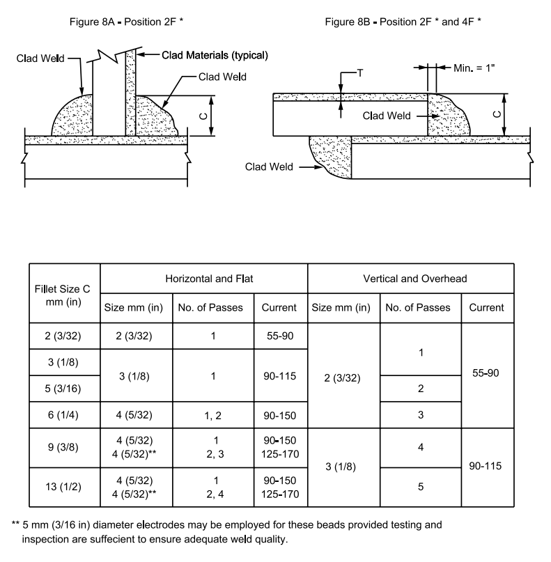
- Fillet Welds
8A Position 2F
8B Position 2F and 4F
TABLE I – Materials and Electrodes for Welding the Clad Side
Welding Clad Plate by SMAW Process
1. Scope
1.1 This standard describes fabricating weldments from clad materials.
1.2 The intent is to ensure welds of acceptable quality in work performed by SABIC Affiliates, vendors, or contractors.
1.3 Nondestructive testing is beyond the scope of this standard.
2. References
Reference is made in this standard to the following documents.
American National Standards Institute (ANSI)
B31.3 Process Piping
American Petroleum Institute (API)
620 Design and Construction of Large, Welded, Low-Pressure Storage Tanks, 1996
650 Welded Steel Tanks for Oil Storage, 1993
American Society of Mechanical Engineers (ASME)
Section IX Welding and Brazing Qualifications
American Welding Society (AWS)
A 5.4 Welding Electrode for Shielded Metal Arc Welding
A 5.11 Specification for Nickel and Nickel – Alloy Welding Electrodes for Shielding Metal Arc Welding
3. General
3.1 The welding of steel integrally clad with other metals and alloys is more exacting than the welding of either one individually. Special attention shall be paid to (a) the accuracy of joint preparation and fit-up, (b) selection of electrodes for individual beads, (c) bead placement, (d) sequence of welding operations, and (e) welding technique.
3.2 This standard addresses butt and fillet welds in the flat, horizontal, vertical, and overhead positions.
3.3 Use the shielded metal-arc (SMAW) process with coated electrodes and direct current reverse polarity (DCRP) power supply.
3.4 Welders qualified under SES W11-F01 for both the cladding material and carbon steel are qualified for welding both sides of the clad material. Welders qualified for carbon steel only may weld the carbon steel backing only. Welders qualified for the cladding material may weld only the cladding.
3.5 Mark each weld (steel backing side and never on the cladding) with a symbol identifying the welder. Where the cladding is welded by a different welder than the steel backing, the cladding welder is to mark his symbol on the steel side followed by a ‘C’.
3.6 SMAW coated electrodes are recommended for welding the various clads using fillers specified in
Table I. Use of other electrodes shall be in accordance with AWS A 5.4.
3.7 Establish welding practices and quality control program in conformance with this standard, ANSI, and ASME Code.
4. Safety
Safe practices prescribed in SES W02-F01 shall be followed on plant sites.
5. Execution
5.1 Joint Preparation
5.1.1 Joints shall be machined, gas cut, ground, or formed by other means to the contours shown on Figure 1. The carbon steel land shall be 0.8 to 1.6 mm (1/32 to 1/16 inch) to prevent alloying into the clad.
5.1.2 Surfaces to be welded shall be cleaned of slag, grease, oil, and other foreign materials by grinding, sanding, or wiping.
5.1.3 In assembly, the land on the clad side shall be butted as close as possible prior to welding the steel backing. Limits for misalignment of the joint are shown on Figure 1.
5.2 Precautions
5.2.1 Dilution – In general, difficulties arise from dilution of the cladding weld deposit with iron and carbon from the steel backing. Alloy is formed with composition between that of the steel backing and that of the cladding weld filler. This dilution occurs in each pass, the final composition of which is a compromise between the underlying pass, the sidewalls, and that of the filler. If the correct electrodes are not used, an alloy subject to cracking is likely to be formed, usually near the substrate. In addition, the composition of the layer at the surface of the clad side weld might be diluted such that its corrosion resistance is reduced.
5.2.1.1 In order to avoid excessive dilution problems in the stainless grades when welding alloy clad, it is desirable to use an electrode with more alloy content than the cladding, particularly for the early passes deposit. As a general rule, this also aids in preventing the formation of alloys subject to cracking. The clad weld beads deposited directly on the carbon steel backing material shall be of a higher alloy content than the clad where possible. (See Table I).
5.2.1.2 Dilution can be reduced by using a stringer bead with the lowest current and highest travel speed as feasible.
5.2.2 Welding Sequence – Always weld the steel side of a joint first. Then, after back-gouging or grinding to clean metal, make the high alloys deposit on the clad side. Never the reverse. Do not attempt to deposit a carbon steel filler on the clad base. If it does not crack on the surface of the bead, it will probably do so in the fusion zone and later fail in service.
5.2.3 Finish Grinding – There are cases where it is either specified or desirable to remove the overlay or weld reinforcement. When this is done, employ clean grinding wheels and take great care to avoid
over-grinding or gouging into the cladding. As an example, remember that the thickness of the cladding on 10-percent clad 6 mm (1/4 in) plate is only 0.64 mm (0.025 in) and that on 20-percent clad 6 mm (1/4 in) plate is 1.3 mm (0.050 in). One slip of the grinder can seriously reduce this thickness or even remove the cladding entirely. Repair any gouges in the cladding by laying down a weld deposit.
5.2.4 Attachments – To avoid damage to the cladding, attach fit-up lugs or clips to the steel side. If tack welds are used, they shall be on the steel side. Do not strike the arc on the cladding, and protect this cladding from flame-cutting spatter.
5.2.5 Handling – Take care to avoid damaging the clad side during handling. Where possible, store plates in pairs with the clad sides in contact. In any event, the cladding shall be on the underside to protect it from being walked on. Design lifting clamps so that they do not dig into the cladding.
5.2.6 Surface Iron Contamination Test – The ferroxyl test used for iron contamination on the clad side is severe and shall not be used unless justified by the service conditions.
5.3 Welding Steel Backing
Weld the steel backing in accordance with SES W05-F02, using the appropriate carbon steel electrodes. Perform this weld prior to welding on the clad side.
5.4 Back-Gouging or Grinding
5.4.1 After welding the steel backing, groove the joint by back-gouging or grinding. The resulting groove shall extend 1.6 mm (1/16 in) minimum below the under surface of the cladding. See Figure 3.
5.4.2 In all cases, the groove shall have a radius of at least 3 mm (1/8 in). In no case shall it to be a V groove. Critically examine back-gouged grooves for flaws and cracks prior to welding the clad side. Do this with a liquid penetrant inspection.
5.5 Welding Clad Side
5.5.1 Refer to SES W05-F04 for general requirements for stainless clad and to SES W05-F11 for nickel clad.
5.5.2 Alloy beads in contact with the steel backing material shall be small stringer beads deposited to minimize substrate penetration. This is necessary to minimize dilution, thus avoiding excessive iron pick-up and possible cracking. See Figure 3.
5.5.3 Suggested pass sequence and conditions are shown on Figures 4 to 8.
5.5.4 Finish beads deposited after the steel backing has been completely covered by weave or stringer beads. Every precaution shall be observed to avoid undercutting along the edges of the finished weld.
5.5.5 Fillet welds shall be carefully made in order to ensure that there is a continuous layer of corrosion-resistant material completely across the cross section of the joint. See Figure 8.
6. Inspection
The amount and type of inspection required depends upon the service conditions and hazards to personnel and property. It is the responsibility of the originator to define the inspection requirements. Inspection shall be in accordance with applicable code(s).
Table I – Materials and Electrodes for Welding the Clad Side

FIGURE 1 – Joint Preparation

FIGURE 4 – Flat Position, 1G

FIGURE 5 – Horizontal Position, 2G

FIGURE 6 – Vertical Position, 3G

FIGURE 7 – Overhead Position, 4G

FIGURE 8 – Fillet Welds