1. SCOPE
2. REFERENCES
3. GENERAL
4. SAFETY
5. MATERIALS
5.1 Structural Steel
5.2 Welding Electrodes
6. JOINT PREPARATION
7. WELDING TECHNIQUE
8. PROCEDURE QUALIFICATION
9. WELDER QUALIFICATION
10. INSPECTION 5
FIGURE
1 Complete Penetration of Prequalified Joints with Limited Thickness (L)
2 Details of Fillet Welds
3 Complete Penetration of Prequalified Joints with Unlimited Thickness (U)
4 Partial Penetration of Prequalified Joints
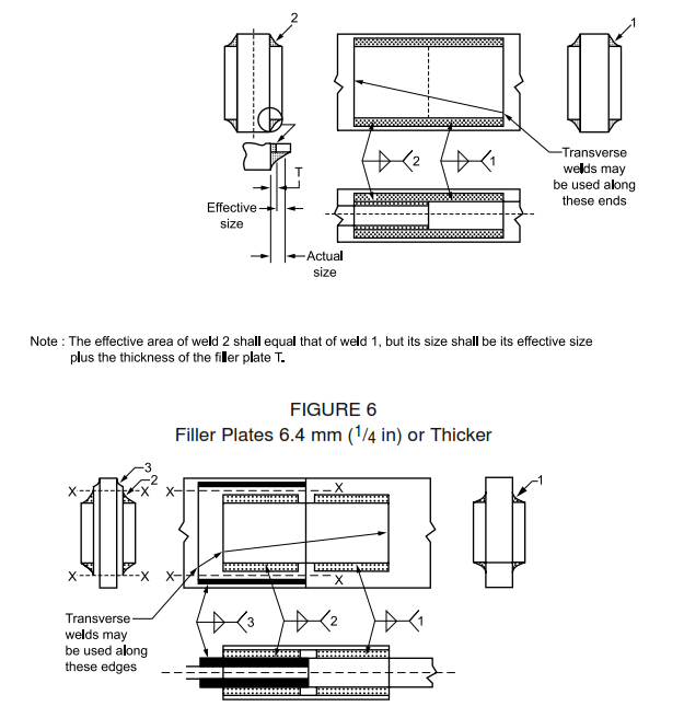
5 Filler Plates Less Than 6.4 mm (1/4 in) Thick
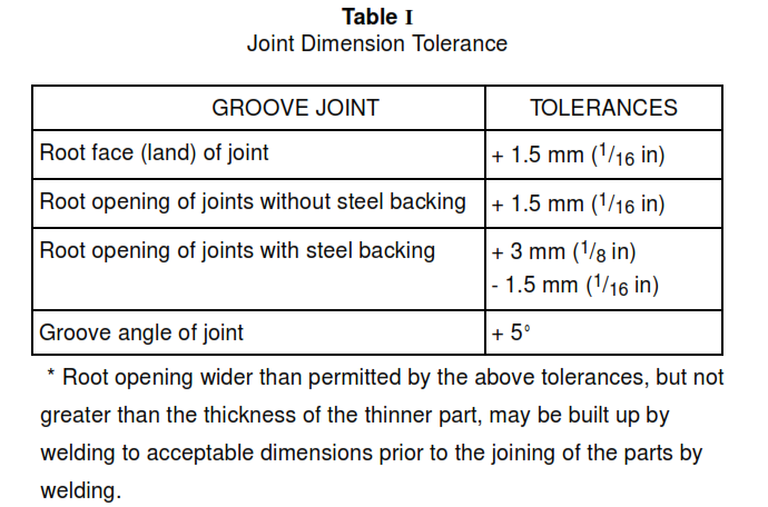
6 Filler Plates 6.4 mm (1/4 in) or Thicker
TABLE
I Joint Dimension Tolerance
II Designation and Classification 6
III Minimum Preheat and Interpass Temperatures 6
IV Minimum Prequalified PJP Weld Sizes
Welding Structural Steel by SMAW Process
1. Scope
1.1 This article is about requirements for groove, fillet, plug, and slot type welding in flat, horizontal, vertical, and overhead positions, by manual and semi automatic metal arc using either straight or reverse polarity, dc or ac, for welding structural steel by the shielded metal arc welding (SMAW) process.
1.2 AWS D 1.1 is a part of this article.
2. References
Reference is made in this standard to the following documents.
American Society of Testing and Materials (ASTM)
A 36 Specification for Structural Steel
A 242 Specification for High Strength Low-Alloy Structural Steel
A 441 Specification for Copper-Cobalt-Beryllium and Copper-Nickel-Beryllium Rod and Bar
A 500 Specification for Cold-Formed Welded and Seamless Carbon Steel Structural Turbine in Rounds and Shapes
A 572/572M Specification for High Strength Low-Alloy Columbium-Vanadium Steels of Structural Quality American Welding Society (AWS)
A 5.1 Specification for Carbon Steel Covered Arc-Welding Electrode
A 5.5 Specification for Low-Alloy Steel Electrodes for Shielded Metal Arc
D 1.1 Structural Welding Code-Steel
American Institute of Steel Construction (AISC)
Manual of Steel Construction
3. General
3.1 In the absence of an applicable building code, the construction shall conform to AISC Manual of Steel Construction.
3.2 Qualification of both the procedure and the welders by an inspector shall be in accordance with applicable code(s).
4. Safety
Safe practices prescribed in SES W02-F01 shall be followed on plant sites.
5. Materials
5.1 Structural Steel
Structural steel shall conform to ASTM A 36, A 572/572M, or A 242.
5.2 Welding Electrodes
5.2.1 Welding electrodes shall conform to AWS A 5.1 and A 5.5, in the E60XX or E70XX series classification.
5.2.2 Only low-hydrogen electrodes shall be used for welding of ASTM 242 (weldable grade) and A 441 (base metals).
5.2.3 Use Class AWS E60XX and E70XX electrodes for ASTM A 36 Steel. Use only AWS E70XX low-hydrogen electrodes for ASTM A 572/572M and ASTM A 242 Steels, except that fillet welds, or partial penetration groove welds, may be made with E60XX low-hydrogen electrodes.
5.2.4 Electrodes shall be of a classification that will provide weld metal of a tensile strength not less than that of the base metal being welded.
6. Joint Preparation
6.1 Surfaces to be welded shall be smooth and free from fins, tears, cracks, and other defects which would adversely affect the quality or strength of weld. Surfaces to be welded shall be free from loose or thick scale, slag, rust, grease, paint, or other foreign material that will prevent proper welding.
6.2 If edge preparation by oxygen cutting is necessary, machine oxygen cutting is preferred. Cleaning, if required, shall be as per 6.1.
6.3 The parts to be joined by fillet welds shall be separated by no more than 4 mm (3/16 in). If the separation is 1.5 mm ( 1 / 16 in) or greater, the leg of the fillet weld shall be increased by the amount of the separation.
6.4 The separation between the mating surfaces of lap joints and of butt joints landing on a backing shall not exceed 1.5 mm ( 1/16 in).
6.5 Irregularities in rolled shapes or plates shall be straightened to permit contact within the limits as per 16
6.3 and 6.4.
6.6 Welds made under the jurisdiction of recognized codes shall meet alignment of tolerances of the applicable code. Otherwise support the pieces to be joined to provide plate alignment within 25 percent of the material thickness or 3 mm ( 1/8 in), whichever is less.
6.7 Dimensions of the cross section of groove welded joints shown on the detail drawings are not to 8 exceed the following tolerances:
Table I
6.1.8 Tack welds shall be made by qualified welders only, with full penetration unless otherwise specified. All cracked tack welds shall be removed.
7. Welding Technique
7.1 The classification of size of electrode, arc length, voltage, and amperage shall be in accordance with SES W05-F02.
7.2 When welding in the vertical position, the progression for all passes shall be upward.
7.3 Preheat and interpass temperatures for welding shall not be less than those listed in Table III.
8. Procedure Qualification
8.1 In general, all fillet welds are deemed qualified, provided they conform to the AWS Code and AISC specifications.
8.2 Qualification tests are in AWS D 1.1 Section 4, Parts B and C.
9. Welder Qualification
9.1 All welders shall be qualified by tests as prescribed in Section 4, Parts B and C, of AWS Code D 1.1, and SES W11-F01.
9.2 Qualification established with any one of the steels permitted by the AWS Code (ASTM A 36, A 242, weldable grade, and A 572/572M) shall be considered as qualification to weld any of the other two steels.
9.3 A welder qualified using an electrode shown in Table II shall be considered qualified for any other electrode in the same group designation, and with any electrode listed in a numerically lower group designation.
10. Inspection
10.1 The inspector shall witness the welding and testing of qualification tests for each welder, or make certain that each welder had previously proven his qualification.
10.2 The inspector may require requalification of any welder who has not used the process for which he has been qualified for a period exceeding six months.
10.3 Critical welds will be inspected by radiographic, magnetic particle, dye penetrant, or ultrasonic methods, at the discretion of inspector.
Table II Designation and Classification
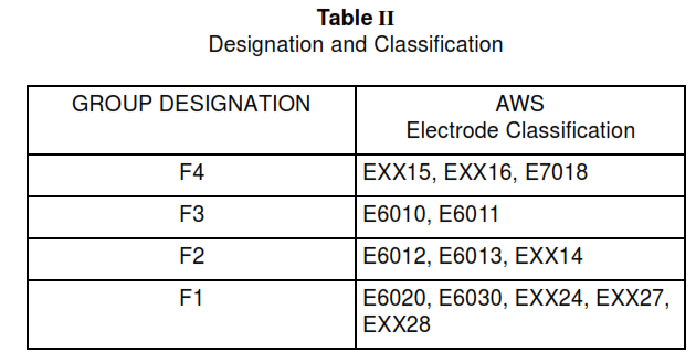
Table III Minimum Preheat and Interpass Temperatures
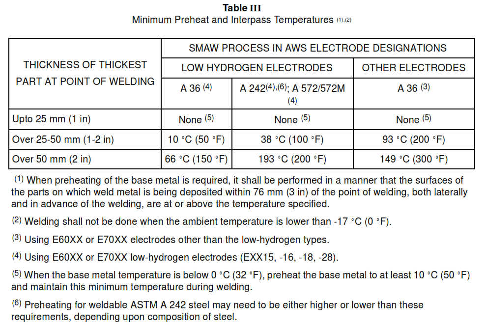
FIGURE 1 – Complete Penetration of Prequalified Joints with Limited Thickness (L)
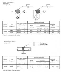
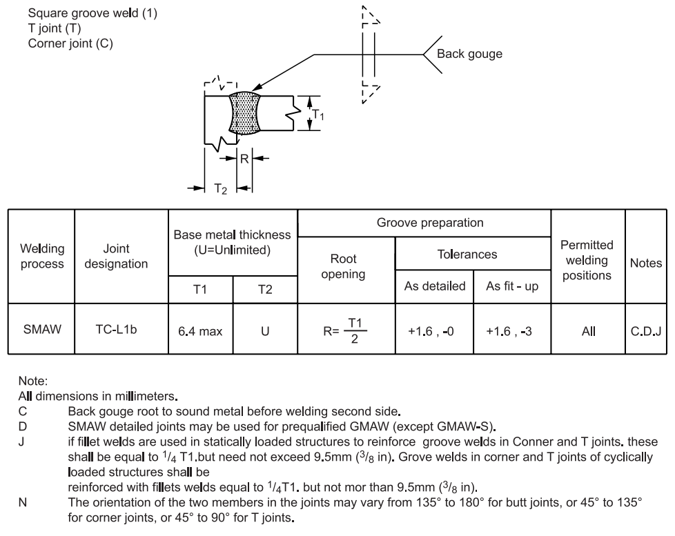
FIGURE 2 Details of Fillet Welds
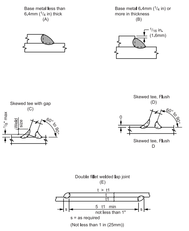
FIGURE 3 Complete Penetration of Prequalified Joints with Unlimited Thickness (U)
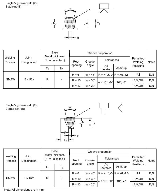
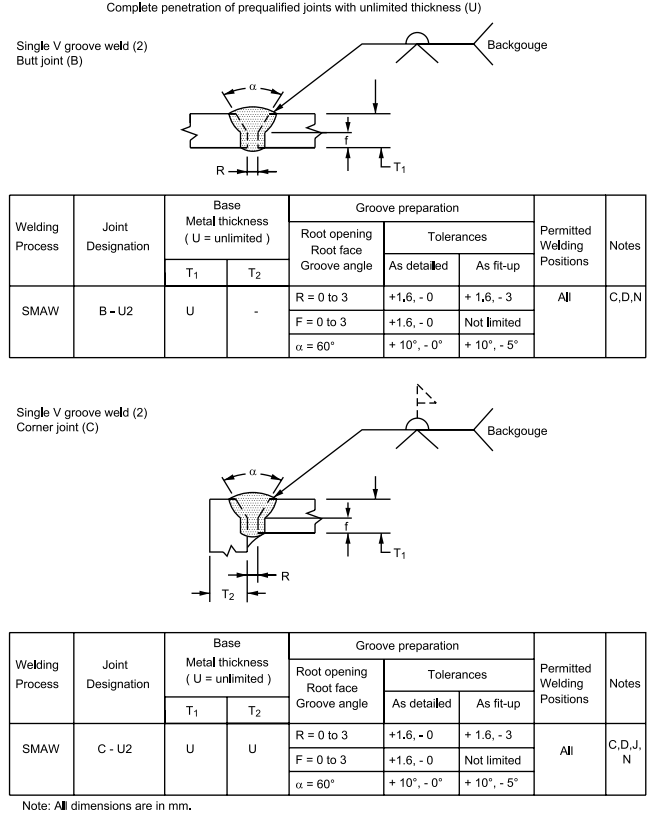
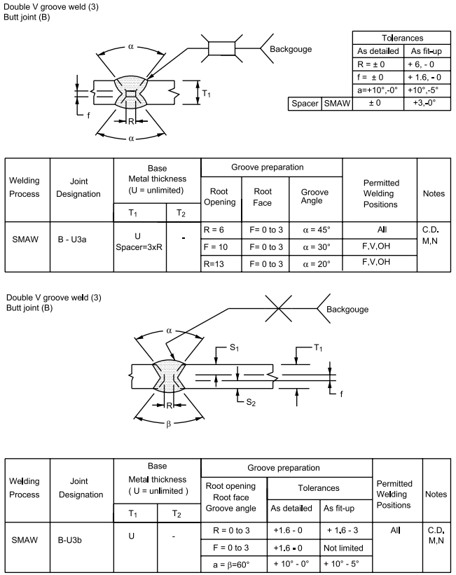
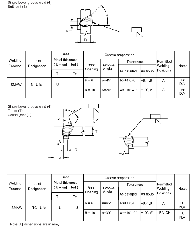
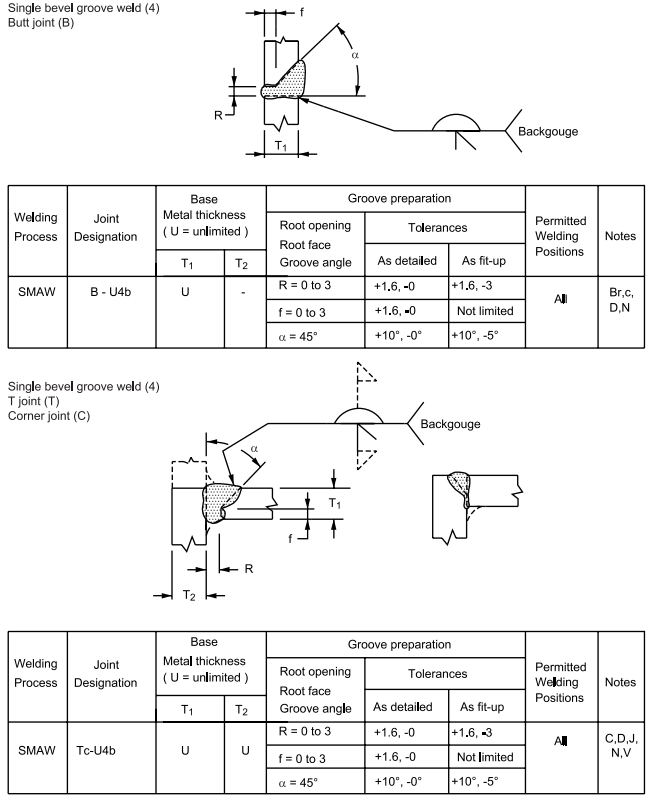
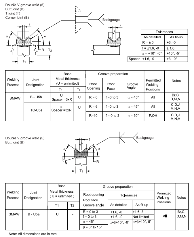
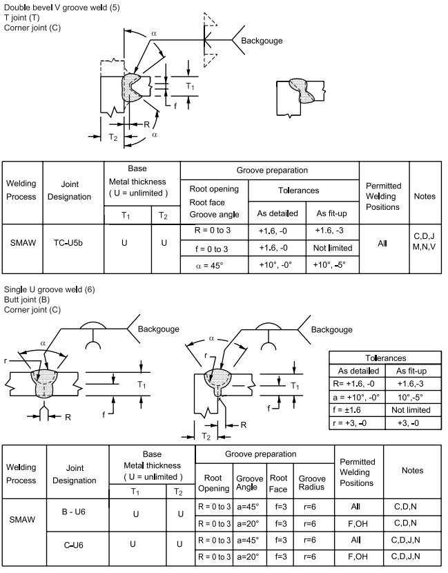
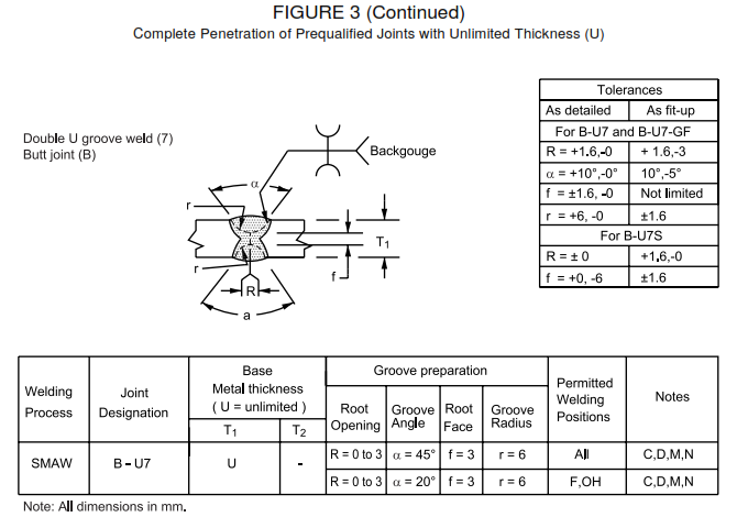

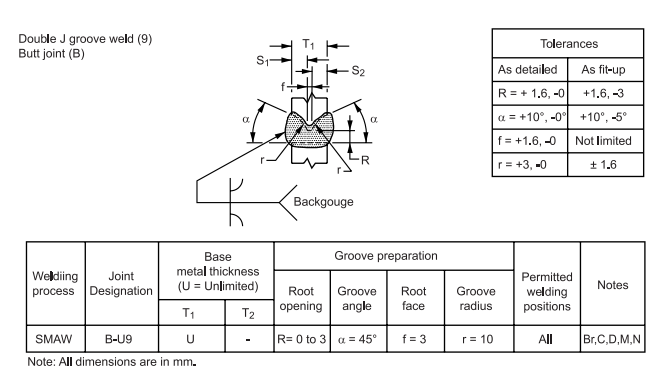
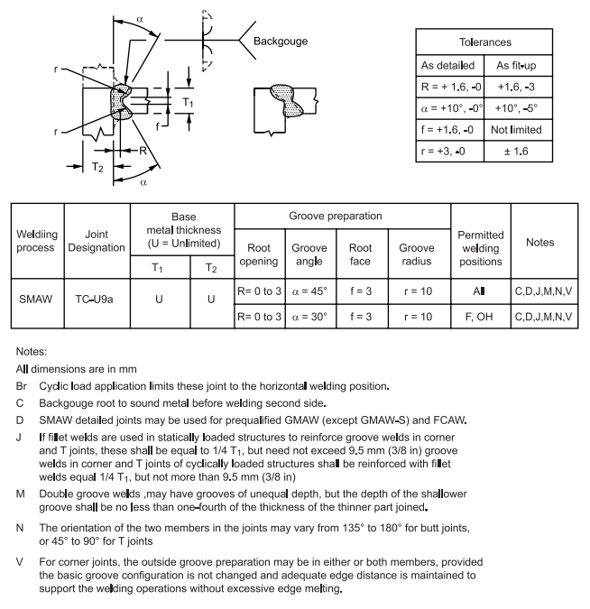
FIGURE 4 – Partial Penetration of Prequalified Joints


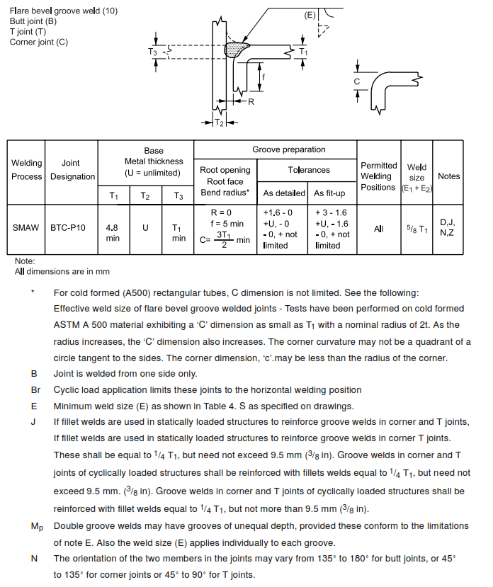

FIGURE 5 – Filler Plates Less Than 6.4 mm (1/4in) Thick