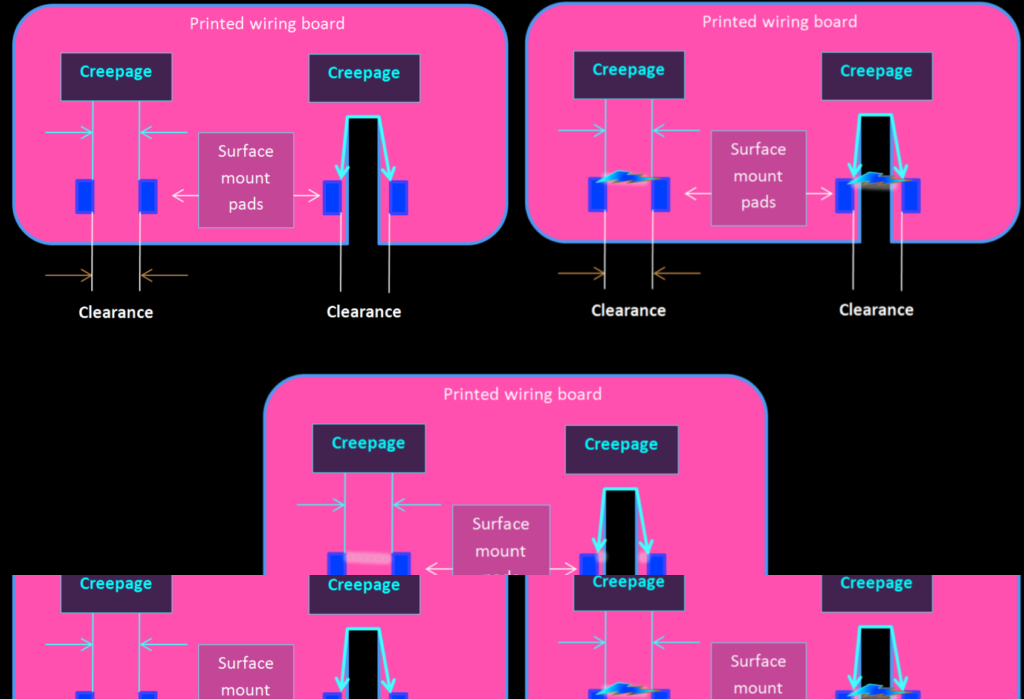
In the world of electrical engineering, ensuring the safety and reliability of electronic components and electrical equipment is very important. Two fundamental concepts that play a pivotal role in this are creepage and clearance. These terms are often used when dealing with circuit boards, connectors, and electrical insulation, high voltage electrical equipment. Understanding their definitions, significance, and the standards governing them is essential for designing safe and effective electrical systems.
What is Clearance?
Clearance refers to the shortest distance through the air between two conductive parts. This is a critical parameter because air, being a good insulator under normal conditions, can become conductive if the voltage difference between the conductive parts is high enough. Adequate clearance helps prevent electrical arcing, which can lead to circuit damage, component failure, or even fire hazards.

Factors Affecting Clearance:
- Voltage Levels: Higher voltage levels require greater clearance distances to prevent arcing.
- Environmental Conditions: Factors such as altitude, humidity, and pollution can influence the required clearance. For instance, higher altitudes reduce air pressure, increasing the risk of arcing.
- Standards and Regulations: Various standards (like IEC, UL) provide guidelines for minimum clearance distances based on different voltage levels and environmental conditions.
What is Creepage?
Creepage is the shortest path between two conductive parts measured along the surface of the insulating material. This distance is crucial in preventing tracking, which is the formation of a conductive path across the surface of an insulator due to contamination or moisture.

Factors Affecting Creepage:
- Material Properties: Different insulating materials have varying degrees of resistance to tracking. The creepage distance required will depend on the material’s properties.
- Surface Contamination: Dust, moisture, and other contaminants can reduce the effective creepage distance, increasing the risk of electrical failures.
- Operating Environment: Environments prone to high humidity, pollution, or other harsh conditions require greater creepage distances to ensure safety.
- PCB with pollution contamination is shown in below picture.

Importance in Design
Properly accounting for creepage and clearance is vital in the design phase of electrical and electronic components. Failure to do so can lead to:
- Electrical Arcing: Insufficient clearance can result in arcing, leading to potential component damage or fire.
- Insulation Breakdown: Inadequate creepage can cause tracking and insulation failure, compromising the safety and functionality of the device.
- Regulatory Non-Compliance: Not adhering to industry standards can result in regulatory non-compliance, leading to legal and financial repercussions.
Industry Standards
Various standards provide guidelines for determining the appropriate creepage and clearance distances. These include:
- IEC 60950-1: Safety of Information Technology Equipment
- IEC 60664-1: Insulation Coordination for Equipment within Low-Voltage Systems
- UL 60950-1: Safety of Information Technology Equipment.
How I used Creepage Distance for Terminations in my Electrical Project?
It’s the shortest path along the surface of an insulator between two conductive parts. All below values mention are taken from International project specification
Outdoor Terminations:
For 13.8 kV systems, each phase needs a minimum creepage distance of 552 mm to ground. For systems operating at 2.4 kV and above, the required distance is 40 mm per kV line-to-line voltage.
Indoor Terminations:
The minimum creepage distance is 25 mm per kV line-to-line voltage.
Enclosed Outdoor Terminations:
If the enclosure is rated NEMA Type 3 or 4, or IEC Type IP54, it’s treated as an indoor termination. If the enclosure has a lesser protection (e.g., NEMA Type 3R), it’s treated as an outdoor termination.
Examples:
- Outdoor 13.8 kV System: Requires 552 mm creepage distance per phase.
- Outdoor 2.4 kV System: Needs 96 mm (2.4 kV * 40 mm/kV).
- Indoor 2.4 kV System: Needs 60 mm (2.4 kV * 25 mm/kV).
Practical Application
Designers must consider the voltage levels, environmental conditions, and material properties when determining the appropriate creepage and clearance distances. Using software tools and adhering to industry standards can aid in ensuring these parameters are met.
Example Calculation:
For a printed circuit board operating at a high voltage in a polluted environment, the required creepage and clearance distances would be greater compared to a low-voltage, clean environment. Using the guidelines provided in standards like IEC 60664-1, designers can calculate the necessary distances to ensure safety and compliance.

Conclusion:
Creepage and clearance are critical parameters in the design and safety of electrical and electronic systems. Understanding their importance and correctly applying the guidelines provided by industry standards can help prevent electrical failures and ensure the longevity and reliability of the components. By carefully considering the operating environment, voltage levels, and material properties, designers can mitigate risks associated with electrical insulation and ensure their designs meet regulatory requirements.