WORK PROCEDURE FOR SPLICING AND TERMINATION OF LOW VOLTAGE CABLES
GENERAL PREPARATORY WORKS (SPLICING & TERMINATION)
- All permanent materials, consumables, equipment to be installed and its accessories, construction area and resources shall be prepared and checked prior to installation works.
- Work Transfer Sheet shall be duly signed and processed by other subcontractors or discipline for the preceding works to avoid confusion and discrepancies in the work responsibilities.
- Special tools shall bear a valid calibration certificates traceable to a national standard indicating calibration validity and periodically (at least six months) checked by a company approved third party laboratory testing facility.
- Electrical materials shall conform to all applicable requirements, standard, and specifications prior to release to be used as part of the work. Refer to Schedule “Q” Att. IV Para 7.1.
- Review all references such as the latest approved for construction drawings, layout, and Technical Scope of Work. Personnel Qualification request for approval shall be submitted 30 days prior to start of the work per Schedule Q para. Attachment IV para 2.1.
- Personnel who will perform the termination and splicing shall be approved terminator by the client.
- Design and Installation of Wiring and Cable Systems shall be in accordance with the NEC as supplemented by SAES-P-104 and/ or as approved Saudi Aramco Standards.
- Cables shall be permanently identified prior to the Splicing / Termination process; Ref SA Std. SAES-P-104 6.10.
- The Vendor Instruction Manual requirements shall be incorporated into the installation procedure. NEC 110.3B; Ref SA Std. SAES-P-104 4.1.
- All Compression Dies / Connectors shall have a Manufacturer’s Reference compression die number and conductor size normally printed or stamped on the connector as required as SAES-P-104 Para. 6.1.
INSTALLATION WORKS OF CABLES
- Low voltage cable with damaged outer jacket should be cleaned and free from accumulation of dust, oil, and moisture using required cable cleaning spray and materials.
- Make sure that the Low voltage cable with damaged portion is free of sharp edge in order to avoid damage when new wrapped around jacket sleeve is installed.
- New wrapped around cable sleeve should be checked if it is cleaned and free from accumulation of dust, oil and moisture. Cleaned the new cable sleeve when required.
- In the damaged portion, wrap around the cable of 3M electrical tape, after then wrap the cable with rubber tape and again wrap the cable of 3M electrical tape.
- Degrease the ends of the over sheath (new wrapped around cable repair sleeve) for a length of about 150 mm.
- Put heat shrink sleeve in centre position and shrink on according to manufactures instruction.
- Repeat the Installation Activities Procedure on other portion of medium voltage cable with damaged outer jacket.
- Repair of damaged outer jacket of LV Cable shall be as per Manufacturer’s Instructions per NEC 110.3.
- All Low Voltage cables shall be installed as per the Company requirement.
- Cable shall not be bent sharp to a small radius handling or installation, for cables the minimum bending radius for PVC/XLPE cables shall be 12 times the overall diameter of Cable.
- The ends of lead sheathed cable shall be sealed with solder immediately after cutting the cables, in case of PVC cable suitable sealing compounds/ tape shrinkable caps shall be used.
CABLE SPLICING PROCEDURE
LOW VOLTAGE & CONTROL CABLE SPLICING WORK SEQUENCE
- Cable jacket removal.
- Position cable to remove cable jacket.
- Remove cable jacket as below dimension:
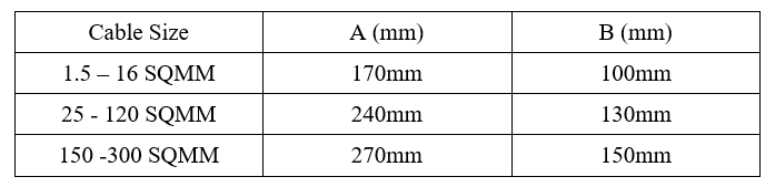
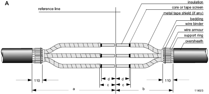
- Insulation Removal and Sleeve Connection.
- Remove cable insulation as 1/2 of sleeve length to connect
- Pull and make position of heat shrink tube for jacket over cable
- Pull and make position of heat shrink tube for insulation over cable insulation of “A” side.
- Connect sleeve by proper tool.
- Shrink Tube for Insulation.
- Make position of heat shrink tube for insulation over the middle of connecting sleeve.
- Shrink the tube from middle to both sides by torch or heat gun (be careful not to damage cable insulation).
- Shrink other tube for insulation as same method.
- Shrink Tube for Jacket.
- Shrink heat shrink tube for Jacket from middle to side by slow (be careful not to damage cable insulation).
CABLE CONNECTION AND TERMINATIONS
- Compression (crimped) type connectors shall be used for splicing and terminating stranded conductors, except as indicated in paragraphs 8.2.3 to 8.2.5 below, and except as specified in SAES-P-111 for grounding conductors. The use of solder lugs is prohibited. Compression terminal connectors for 4/0 and larger conductors shall be two hole NEMA design. All compression connectors for 8 AWG and larger conductors shall have a manufacturer’s reference compression die number and conductor size printed or stamped on the connector.
- Compression in compression connectors is accomplished by means of a compression or crimping tool. Connectors in which compression is accomplished by means of bolts, set screws, etc., are mechanical, not compression connectors.
- All compression connectors shall be tinned copper.
- Spring pressure type twist-on connectors, and pressure set screw connectors with insulating caps are permitted (a) for lighting and receptacle circuits in non-hazardous locations, and (b) in non-industrial applications.
- Cable terminators relying on inwardly protruding flat springs or tines for grounding the metallic sheath or armor are prohibited.
- Check proper terminals and crimping die are used on cable and that crimping procedure is proper.
- Inspect cables for physical damage and proper connection in accordance with single line diagram.
- Cable connections shall be torque tested to manufacturer’s recommended values or values recommended in SA-P-000.
- Verify proper terminals and crimping die are used on cable and that crimping procedure is proper.
- Verify cable colour coding or phasing.
The following torque table is for general reference. The manufacturers recommended torque values should be used. In the absence of manufacturer’s recommendations, the following values are the recommended maximum torque values that should be applied. Note that grade 5 hardware should be used in switchgear as a minimum.

TOOLS AND EQUIPMENT FOR SPLICING AND TERMINATION
Tools and equipment needed should be in good condition and must be checked by Supervisor / Safety Engineer prior to use in the construction area. These includes but not limited to:
- Electrical Hand Tools
- Multi Tester
- Term Shield Conn.
- Semi-conductor peeling device
- Insulation remover
- Conical cutting tool with conical knife
- Gas torch
- Crimping tool hydraulic
- Diameter measuring tape
- Nylon Ropes
- Splicing Knife
- Other Relevant Tools
All tools utilized in a classified area should be intrinsically safe and suitable for hazardous areas.
Industry Codes and Standards for Splicing and termination
NFPA 70 National Electrical Code (NEC)
IEC 60840 International Electrotechnical Commission (Power Cables with Extruded Insulation)
SAFETY PRECAUTIONS
- Secure the approved work permit from the concerned Contractor Representative before starting any work.
- Fire Watcher with Fire Extinguisher shall be assigned at work area whenever there is hot work.
- All electrical tools shall be checked and color-coded.
- Hazardous area and its precautionary measure requirements shall be properly discussed to the working crew following all safety requirements.
- Continuous monitoring and checking shall be conducted by concerned supervisor/foreman to detect and correct unsafe practices while performing the work activities.
- Provide warning sign and sufficient barricade on working areas to avoid unauthorized entry. Only assigned personnel shall be allowed in the area.
- Safety harness with double lanyards shall be used when working at elevated temporary platforms (1.8 meters and above).
- Safety Supervisor shall monitor the work activities to help and protect all assigned workers against exposure to safety hazards. He shall ensure that Personal Protective Equipments (PPE’s) are being supplied and used and shall comply with Contractorand Client applicable general instruction and standards.
- Toolbox meeting shall be conducted by Electrical Supervisor daily so that work activities will be properly coordinated to all concerned and all safety measures will be carried out on the entire work duration.
- Housekeeping shall be maintained and working area shall be kept clean and tidy in accordance with Site Housekeeping Procedure.
- Job Hazard and Risk Assessment of this procedure shall be disseminated and explained to workers for safety awareness.