PROCEDURE FOR INSTRUMENT CABLING WORKS

  PROCEDURE FOR INSTRUMENT CABLING WORKS Pre-installation Activities Prior to cable laying/pulling, ensure that the cable trench, duct bank, raceway, …

Read more

PROCEDURE OF INSTRUMENT PIPING AND TUBING INSTALLATION

GENERAL REQUIREMENTS

  1. Study and prepare all installation requirements, and related references such as approved for construction drawings, layout, P&ID, hook-up drawings, Technical Scope of Work, Work Permit requirements and work procedures.
  2. All permanent materials (including fabricated and pre-fabricated supports) and consumables to be installed shall be prepared and checked prior to installation works.
  3. Ensure that working areas are ready for installation to include availability of scaffolding if needed, supports and access to avoid delays of the activities.
  4. Ensure that the tapping point and tubing routes are well coordinated with piping, mechanical and related construction group to avoid conflicts that would cause delay in the approved schedule. Study tubing routes and possible locations of supports for fabrication if needed.
  5. Ensure that manpower, equipment, tools and other logistics are ready and prepared for installation.                                                                     

PROCEDURE OF INSTRUMENT PIPING AND TUBING INSTALLATION

  1. Survey and study the designated location of field instrument in accordance to the EPC latest issued approved for construction drawings this to include the hook-up drawings, P&ID and layouts. Should there be discrepancies or obstructions found in the construction drawings, technical queries should be raised to EPC for further site instructions.
  2. Routes of instrument air branch supply lines shall be taken from the top of the header or air manifold that is accessible for maintenance.
  3. Upon identification of final specific routes of air piping, fabricate and install corresponding supports and brackets for instrument pipes and tubing as per Saudi Aramco Standard and EPC approved for construction drawing.
  4. Ensure that installed pipes, tubes and its fittings are damage free. Good handling practice shall be adhered to prevent scratches on pipe and tubing. The following points shall be followed.
    a) Pipe or tubing shall not be dragged out by a tubing rack and shall be carefully lifted by at least two people.
    b) Pipe and tubing shall not be dragged across concrete, asphalt, gravel or any other surface which could scratch it.    c) Pipe or tubing shall not be stored/laid down on the ground at site where personnel can stand on it. Sufficient measures shall be taken to protect and preserve tubing at site (i.e. segregated storage, wooden blocks, etc.)
  5. All tubing shall be covered with fire blanket when grinding, drilling, and welding works is being carried out in the area.
  6. Tubing shall be installed in a manner that allows for calibration of instrument and removal of adjacent instruments, equipment and tubing. All piping and tubing shall not be pocketed.
  7. All tubing shall be installed in a neat manner with no signs of crimping, flattening, or bends with radius too small. Tubing shall not be marked or scored. Slope angle of tubing shall be minimum 1 :12.
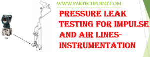
  8. For gas and vapor service, pressure transmitters shall be mounted above and as close to pressure taps as possible while still maintaining accessibility. Impulse lines shall slope continuously downward from transmitter to root valve such that they are self-draining (minimum one inch per foot).
  9. For liquid or condensing service, pressure transmitters shall be mounted below the pressure taps. Impulse lines shall slope continuously upward from transmitter to root valve such that they are self-venting (minimum one inch per foot).
  10. Tubing must have a minimum length of straight run adjacent to bend to correct installation of fittings.
  11. The length of unsupported tubing to its final location for single tubes shall not exceed 0.5 meters. Where signal tubing run over 6 meters, 150mm diameter loop shall be provided. For meter in flow control loop, any piping and impulse tubing shall not exceed 6 meters.
  12. Tubing shall be assembled with the specified compression fittings in accordance with the manufacturer’s instructions. The proper tools recommended by the manufacturer, shall be use to assure adequate engagement and tightness. Tube union can be used where approved by EPC.
  13. Tubing shall be blown through the clean dry air after installation and immediately prior to connection.
  14. Open end of the installed tubing shall be capped or taped to prevent entry of foreign matter.
  15. Manufacturer’s instructions shall be adhered at all times in installing compression fittings.
  16. Tube fittings installed in individual or parallel tube runs shall be staggered and raised to allow tube removal or reinstallation without damaging the individual tube or adjacent tubes.
  17. Proper sealant should be used for thread connection. (Special proper sealant shall be used for the connection more than 150°C process line).

Read more

Electrical conduit Installation Aboveground & Undergroud Techniques

This article is about Electrical conduit Installation Aboveground & Undergroud Techniques  and focusing to the engineers, technicians and supervisors. You will find lot of documents related to this article. Just navigate our website  www.paktechpoint.com  and find more articles. Please! Do not forget to subscribe our You tube channel also. Thanks in Advance.

PLEASE SUBSCRIBE OUR PAKTECHPOINT YOUTUBE CHANNEL

To ensure that Electrical Conduit Installation is performing safely, efficiently and in accordance with good working practice, as per International standards and Saudi Aramco.
This article is applicable to all PVC, GRS and EMT conduit installation activities, which are to be installed.

Pre-Installation Activities Preparation

1.  Electrical materials shall be new, unused and free of damage.
2.  Fitting intended to connect to an unthreaded opening in a box or enclosure shall be provided with secure means. A fitting provided with locknut shall have a thread projection, when measured from the shoulder stop to the end of the threads along the major axis of threaded projection.

3.  Rigid connector, couplers and stopping plugs shall be made of steel galvanized inside and outside. On conduit runs exceeding 7.5m an inspection installation shall be provided.
4. A threaded hole for connection to conduit that is tapped completely through the wall of box shall permit proper attachment of a conduit bushing to wrench -tightened conduit.

5.  Make sure conduit materials are stable when storing or handling. Suitable lifting equipment for heavy lifts shall be used. Manual handling/lifting of smaller bundles

of conduit (i.e., bundles of 1 O or less) shall be applied at a minimum of two points by qualified personnel.
6. Transport and store the conduits and accessories by methods in accordance manufacturer’s instructions to avoid product damage.
8. Store conduits in a planned and orderly manner that does not endanger employee safety. Ensure stacks and tiers are stable and stacked to aid safe handling and loading.
9.  Do not store conduits under power lines or where materials may block egress or emergency equipment.
10. Conduits shall be stored in a clean, dry and secure location. Especially avoid places where water might accumulate or where significant dust or dirt is present. If such a location is not available, materials shall be stored on pallets or other means to rise above the floor and possible water levels, and wrapped in protective plastic sheeting at both ends of the bundle.

11. Should any event such as water leaks occurs, that could damage stored  materials, the affected material shall be re-inspected for damage and necessary replacement shall be obtained.
12.  Place steel conduit bar stock in racks or stack and block them on a firm, level surface to prevent spreading, rolling, or falling. Use either a pyramided or battened stack. Step back battened stacks at least one unit per tier and securely chock them on both sides of the stack.

13. Place or store materials so they do not interfere with access ways, doorways, electrical panels, fire extinguishers, or hoist ways. Do not obstruct access ways or exits with accumulations of scrap or materials. Aisles must be wide enough to accommodate forklifts or firefighting equipment.

14.  Store conduits inside buildings under construction at least 6 feet away from any hoist way or inside floor openings, and 10 feet away from an exterior wall that does not extend above the top of the material stored.
15. Unload conduits so that personnel are not exposed to the unsecured load. PVC coated rigid steel conduit shall be handled in manners that prevent injury to the PVC coating by stones and any other material.

16. Touch-up damaged factory finished surface. Use touch-up materials to match original. Do not paint over markings or labels.

17 PVC materials not identified as “sunlight resistant” shall be stored in areas shaded from direct sunlight.
18.  Manufacturer’s recommendation will be followed in threading and bending of PVC coated, GRS conduits.
19. Conduit ends shall be sealed with duct seal or end bells wherever it’s required and applicable.
20. Follow Conduit run to be completed and cleaned of construction debris by blowing with clean air prior to Cable Pulling.

Installation Activities (Above Ground RGS Conduit Installation)

1 Fabricate and install braces and supports. Welding shall be in accordance with approved procedures. Welding of braces and support should be sealed and full weld. Clean and properly primed all weld supports.
1 Lay RGS (Rigid Steel Galvanized) conduit using adequate tie wires as temporary supports. Ensure correct fittings, offsets, route and elevation. Mark the required location of supports as shown on plan drawings.

2 Check Maximum total bend radius for each conduit. Run shall not contain 4-90° (total of 360°) between pull points e.g. conduit bodies and boxes.
3 Left all empty conduits with nylon pull cord.
4 Install Conduit parallel with or at right angles to walls, columns, beams etc.,except as indicated on drawings.
5 After cutting of conduit pipes, remove any sharp burrs using a half round file.
6 Lubricate threads of plugs, junction boxes and other fittings with rust preventive  grease compounds.
7 Care should be taken to avoid wrench damage to conduit coating during  tightening.
8 Field cut of metal support, and exposed conduit thread should be touch-up with  zinc rich paint.
9 Provide Sealing for all conduit wall penetration, penetration of conduit should be thru metal sleeve, sealing should be same as the rating of the wall.
10 Install metal junction boxes levelled and supported with appropriate hubs, locknuts and bushings.
11 Install Conduit bodies and Pull Boxes in a vertical manner position.
12 Raceway shall be provided with expansion fittings where necessary to compensate for thermal expansion and contraction.
13 Install the conduit drain fittings at the lowest elevation of the installed conduits in order to drain the accumulated liquids that might occur due to condensation which is known to be a problem when raceway was exposed to different temperatures.

14 Conduits that cross hazardous location boundaries shall terminate in the open  air at both ends of the conduits.
15 Small gap shall be allowed between cable tray ends and conduit openings applicable to be dropped in conduits.
16 Conduit fill shall not exceed the maximum fill as specified in NEC Chapter 9″. 6.3.17 Installed conduit stub-up to be protected, open ends plugged, bends free of deformities, and hard plastic conduit spacer installed as required.


Read more

error: Content is Protected.