CABLE TRAY INSTALLATION PROCEDURE

This article is about cable tray installation as per international standard of NEMA VE1, NEMA VE2 and ARAMCO standards.

CABLE TRAY INSTALLATION PROCEDURE / METHOD STATEMENT

1. All cable trays & accessories received at site shall be inspected, handled and stored upon receipt in accordance with Project Procedure for Material Control.

2. Inspections shall be conducted by the Electrical contractor, Electrical QC Inspector and Company representative in accordance with Inspection & Test Plan (ITP) inspection test plan.

3. Cable trays and covers for electrical & instrumentation cables shall be manufactured from hot dip galvanized carbon steel matching to project requirement specifications.

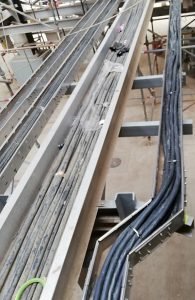
4. Cable tray installation shall be self supporting type with a wide flange (48mm or 72mm or 100mm) in accordance with cable cross section.

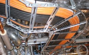
5. Cable tray installation shall preferably be installed flat in buildings or operating structures.  Tray shall run as far as possible under flooring and walkways.  Only in special cases shall cable trays be installed vertically or on edge.  On vertical cable trays and on edgewise – horizontal cable trays, each cable shall be fixed with 20mm wide stainless steel strips (two per meter).  On horizontal cable trays, laid flat cables are fixed in group (one fastening for every two or three meters).  On pipe racks, cable tray shall run on the top most level(s).

6.  Cable trays shall be fixed onto standard steel shapes, welded to steel structures or fixed on to concrete structures with self-drilling dowels.  Distance between fixing points and cable tray support spacing shall be a maximum of three meter for ladder type tray and two meter maximum for perforated tray so as to avoid strain on cable trays.

7. Cable tray installation shall be designed to carry a load of 100kg/m. All cable trays shall be perforated or ladder type to avoid the retention of water and to allow fastening of the cables.

8.  Cable trays shall be provided with covers where there is high risk of mechanical damage during normal operation or maintenance periods.  Cover fabrication shall be the same as that of cable trays themselves and shall be fixed on cable trays with proper clips recommended by cable tray Manufacturer/Vendor and comply with project required specification.

9.  The number of single or multi-conductor cables rated 11kV, 6.6kV, 1kV or less in cable trays shall include an allowance of 20% extra space for future expansion.

10.  Separate racking/trays shall be installed for the following electrical systems, generally arranged top to bottom manner.
a.) HV and MV cables
b.) LV Power, Lighting and Control cables for non-instrument cables
c.) Instrument Cables (Electronic and Signal Cables)
d.) Telecommunication Cables

Read more

WORK PROCEDURE FOR CABLE PULLING

WORK PROCEDURE FOR CABLE PULLING The purpose of WORK PROCEDURE FOR CABLE PULLING generating this method statement is to define the …

Read more

ELECTRICAL FIELD TEST SF6 PAD MOUNTED SWITCHGEAR

MECHANICAL INSPECTION SF-6 PAD-MOUNTED SWITCHGEAR 1.      Inspect for physical damage and compare nameplate data with plans and specifications. 2.      Perform mechanical operations tests in …

Read more

Junction Box Requirements for Foundation Fieldbus

Junction Box Requirements for Foundation Fieldbus


There are following requirements.
 All trunk and spur connections in the field junction boxes, including pass through trunk pairs without spurs, shall be terminated on wiring-blocks specifically made for FOUNDATION™ Fieldbus networks.
Each FF field junction box shall be sized according to the number of segment trunk cables and devices that are connected through it. The maximum JB size allowable including installed spares shall provide termination blocks for the connection of three segments with 12 spurs on each. There shall be 20% installed spare device capacity in each Junction Box i.e. sufficient free connection points in the termination blocks to meet this requirement.
The ‘wiring block’ shall meet the following requirements:
  • Two (2) dedicated connections for the fieldbus homerun/trunk cable.
  • Trunk connections shall be non-sparking (no arcing) i.e., Ex nA.
  • Integral short circuit protector for spur connections, maximum current to spur shall be no more than 60 mA.
  • Spur connections shall be rated nonincendive (energy limited), i.e., Ex nL and shall have ‘live disconnect’ capability (including junction boxes).
  • Pluggable (removable) ‘trunk’ and ‘spur’ connectors with retaining screws.
  • LED indicator for each spur connection indicating when a spur is shorted and is in overcurrent mode.
  • LED to indicate when bus power is available.
  • Segment wiring block shall be CENELEC (ATEX) Ex nA[L]; Class 1, Zone 2, Gas Group IIC.
  • Wire capacity: 12-24 AWG.
  • Temperature range -45 to 70 deg C.
  • DIN rail mounting.
  • Available in four (4) spur and eight (8) spur configuration.
  • A warning label must be prominently affixed on the junction box door (inside) stating the following: (red lettering with white background) “WARNING: Explosion Hazard – Do not connect or disconnect the ‘trunk connections’ on the wiring-block unless power has been switched off or the area is known to be non-hazardous.”
  • An information label must be prominently affixed on the junction box door (inside) stating the following: (black lettering with white background) “The spur connections may be connected or disconnected while the circuit is live, i.e., you may connect or disconnect the spur on the wiring-block or at the device without sniffing the area for combustible gasses.”
  • The wiring-blocks shall be mounted vertically in the field junction box.
  • The DIN rail(s) in the junction box shall be designed with enough spare length to allow the future addition of one 8-spur or larger wiring-block.
  • Junction Boxes shall contain only FF signal wiring.
  • The junction box shall be a single door IP65 box.


Read more

error: Content is Protected.