A current transformer (CT) is an essential component in electrical systems, used for measuring electric currents. It plays a crucial role in facilitating the monitoring, protection, and control of power systems. The primary purpose of a current transformer is to transform high currents in power systems into measurable, standardized currents suitable for instruments and relays.
Functions of Current Transformers
Here’s a summary of the functions:
- Convert Primary Power Signals:
- Convert primary power signals to manageable values for various applications.
- Indicating Meters:
- Provide accurate current measurements for indicating meters.
- Revenue Metering:
- Facilitate precise current measurements for revenue metering purposes.
- Protective Relay Systems:
- Enable protective relay systems by transforming currents to appropriate levels.
- Power Generation:
- Support power generation processes by monitoring and managing current flow.
- Plant Monitoring Systems:
- Contribute to plant monitoring systems by providing essential current data.
- Fault Recorders:
- Assist fault recorders in identifying and recording electrical faults accurately.
- SCADA (Supervisory Control and Data Acquisition):
- Integrate with SCADA systems to monitor and control electrical processes.
- Overall Electric Grid Monitoring:
- Play a vital role in monitoring the overall electric grid at both local dispatch and ISO (Independent System Operator) levels.
- Building (Energy) Management Systems:
- Support building energy management systems by providing current data for HVAC (Heating, Ventilation, and Air Conditioning) and refrigeration.
- Load Control:
- Contribute to load control systems by providing insights into current consumption patterns.
Compliance & Standards
- IEEE C57.13: Standard Requirements for Instrument Transformers
- This IEEE standard specifies general requirements for instrument transformers, which include both current and voltage transformers. It covers design, testing, and performance criteria.
- IEEE C57.13.6: Standard for High-Accuracy Instrument Transformers
- This is an extension of the IEEE C57.13 standard and focuses specifically on high-accuracy instrument transformers. It may include additional requirements and testing procedures to ensure precise measurement capabilities.
- IEC 60044-1: Current Transformers
- This IEC standard outlines the specifications and requirements for current transformers. It covers topics such as accuracy, performance, and testing procedures for current transformers used in various applications.
- IEC 60044-6: Requirements for Protective Current Transformers for Transient Performance
- IEC 60044-6 provides specific requirements for protective current transformers, with a focus on their transient performance. Transient performance is crucial in applications where fast and accurate response to transient conditions is required, such as in protective relaying systems.
- IEC 61869-2: Additional Requirements for Current Transformers
- This IEC standard specifies additional requirements for current transformers. It may address specific aspects not covered in other standards, providing comprehensive guidelines for the design, testing, and performance of current transformers.
Basics of Current Transformer
A basic current transformer (CT) is a type of instrument transformer designed to measure electric currents. It plays a crucial role in power systems by stepping down high currents to levels suitable for monitoring and protection devices.
How Current Transformer Works?
A current transformer (CT) works based on the principles of electromagnetic induction. Its primary purpose is to step down high currents in power systems to levels suitable for measurement and protection devices. Here’s how it works:
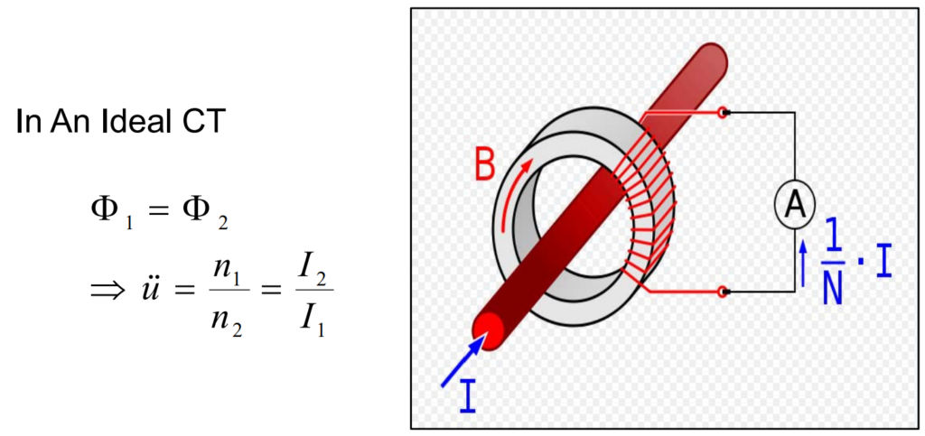
Current Relationship Equation:
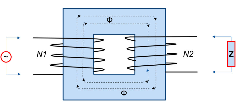
The equation “I2 / I1 = n2 / n1” signifies the relationship between the secondary current (I2), primary current (I1), and the turns ratio (n2 / n1).
Magnetic Flux Relationship Equation:
The equation “Φ2 = Φ1” indicates that the magnetic flux (Φ) in the core is conserved, meaning that the flux generated by the primary current is equal to the flux linked to the secondary winding.
Turns Ratio (n) Equation:
The expression “n = n2 / n1” defines the turns ratio as the ratio of the number of turns in the secondary winding (n2) to the number of turns in the primary winding (n1).
- When an alternating current (AC) flows through the primary winding, it generates a magnetic field in the core. This magnetic field induces a voltage in the secondary winding, and according to Faraday’s law of electromagnetic induction, this induced voltage is proportional to the rate of change of magnetic flux.
- The turns ratio (n) plays a crucial role in determining the relationship between primary and secondary currents. It establishes how much the current is stepped down in the secondary winding relative to the primary winding.
- The equations emphasize that, in an ideal scenario without losses, the secondary current is directly proportional to the primary current based on the turns ratio. In other words, if you double the number of turns in the secondary winding while keeping the primary current constant, the secondary current will also double.
Ignoring Magnetic and Resistive Losses:
The statement “Ignoring Magnetic and Resistive losses for the moment” acknowledges that, in practical situations, losses such as magnetic and resistive losses can occur. In an ideal case, these losses would be neglected.
Real CT Analyzer Model
The 3 parts of the CTA model:
- Winding Ratio (Purely the Ratio of Turns)
- Magnetic & Core Losses from Hysteresis, Gaps, Inductance, Eddy Currents
- Winding Resistance Losses
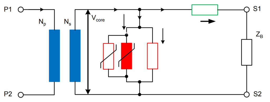
The CT analyzer model comprises three essential components, the first of which focuses on the winding ratio. This parameter, determining the turns relationship between primary and secondary windings, is fundamental for accurate current transformation.
The second component addresses magnetic and core losses, including hysteresis, gaps, inductance, and eddy currents. Quantifying these losses is crucial for evaluating the efficiency and accuracy of the current transformer under diverse operational conditions.
Winding resistance losses form the third component of the CT analyzer model. This part evaluates the resistive elements in both primary and secondary windings, ensuring they adhere to acceptable limits for efficient transformer performance.
In summary, the CT analyzer model provides a comprehensive analysis of current transformers. It assesses the winding ratio, magnetic and core losses, and winding resistance, ensuring compliance with industry standards and specifications. This thorough examination is vital for verifying accuracy, efficiency, and reliability across various operating conditions.
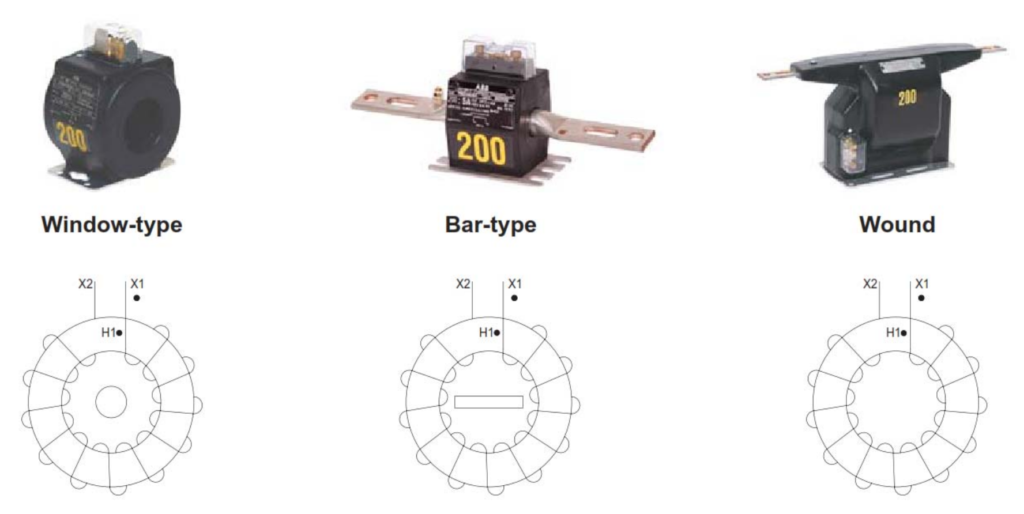
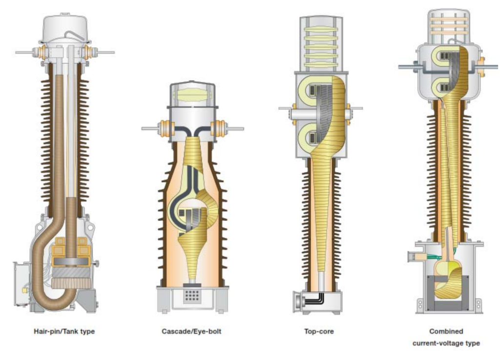
CT Construction Types
Current transformers (CTs) are constructed in various types to meet specific application requirements. The construction types are designed based on factors such as accuracy, insulation, and the intended use of the CT. Here are common CT construction types:
- Wound Primary CT:
In this type, the primary winding is wound directly onto the core. It is a straightforward construction suitable for applications where accuracy requirements are not extremely stringent.
- Bar-type CT:
- Bar-type CTs have a primary winding in the form of a bar or a tube that surrounds the conductor carrying the current to be measured. They are often used for high-current applications.
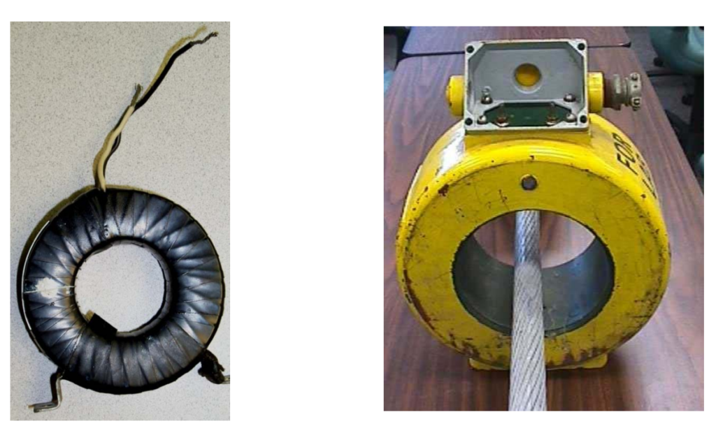
- Window-type CT:
- These CTs have an opening or “window” through which the primary conductor passes. The primary winding is typically wound around the core. Window-type CTs are easy to install and are commonly used in retrofit applications.
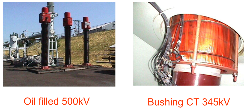
- Bushings CT:
- Bushings CTs are integrated into the bushings of electrical equipment such as transformers or circuit breakers. They provide a compact and integrated solution for measuring current within the equipment.
- Oil-filled CT:
- In oil-filled CTs, the core and windings are immersed in insulating oil. This construction is often used in outdoor or high-voltage applications where additional insulation and cooling are required.
- Gas-insulated CT:
- Gas-insulated CTs use insulating gas, such as sulfur hexafluoride (SF6), for insulation. They are compact and suitable for applications where space is limited.
- Resin-cast CT:
- Resin-cast CTs have the windings and core enclosed in epoxy resin. This construction provides excellent insulation and protection against environmental factors.
- Polymer-insulated CT:
- Polymer-insulated CTs use high-strength insulating materials for both the core and windings. This construction offers lightweight and durable solutions for various applications.
- Split-core CT:
Split-core CTs can be opened, allowing them to be installed around an existing conductor without the need to disconnect the circuit. This design simplifies installation and maintenance.

- Shielded CT:
- Shielded CTs have additional magnetic shielding to reduce the impact of external magnetic fields. This construction is suitable for environments where electromagnetic interference may affect accuracy.
- Multicore CT:
- Multicore CTs have multiple primary windings, each connected to a separate core. This design is used when measurements of different currents are required within the same device.
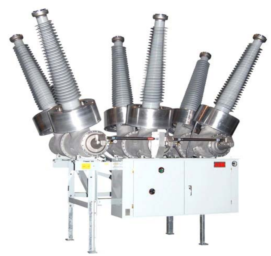
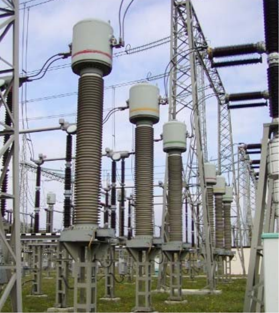
- High Voltage Current Transformer
The choice of CT construction type depends on the specific application, the level of accuracy required, environmental conditions, and other factors relevant to the electrical system.
Current Transformer Cores
Current transformer (CT) cores are a critical component of CT construction, serving the purpose of creating a magnetic circuit that links the primary and secondary windings. The core material and design significantly influence the CT’s performance characteristics, including accuracy, saturation, and frequency response.
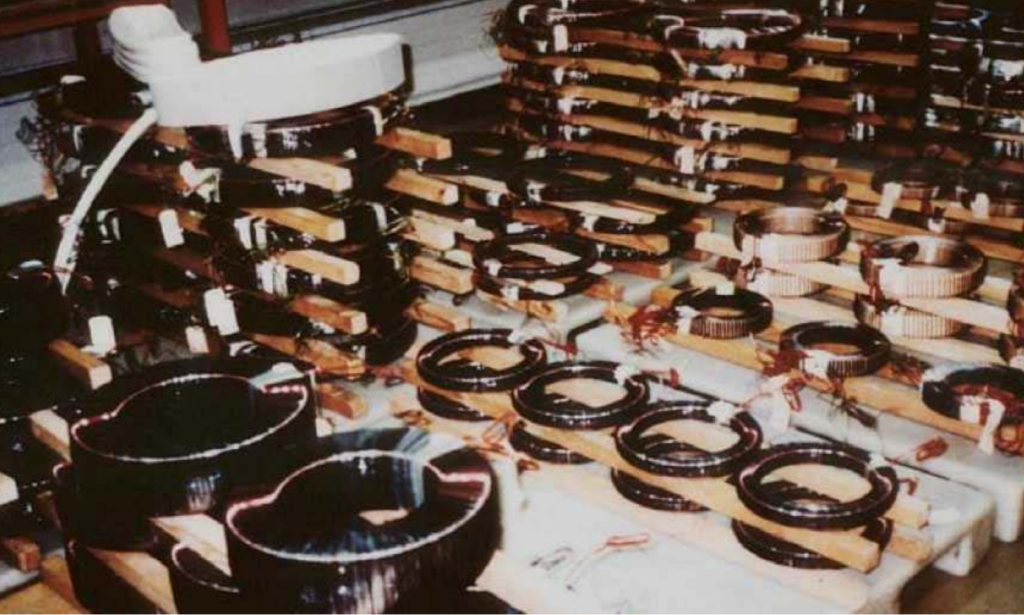
CT with Multiple Cores
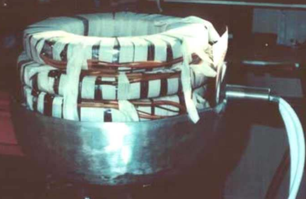
Insulation of a Core Pile

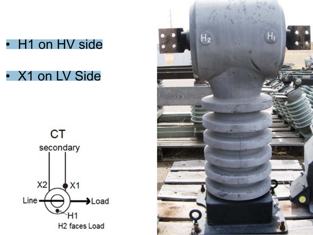
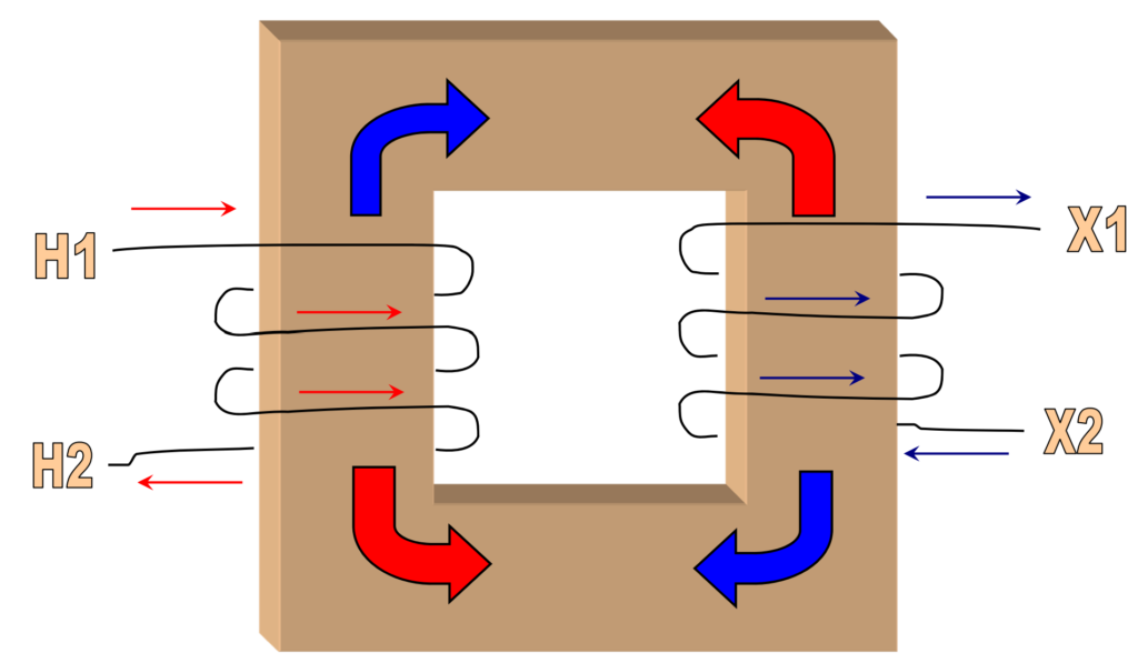
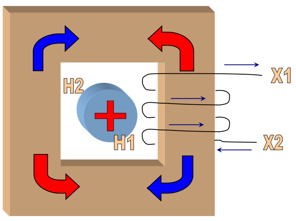
Polarity and Terminal Marking
Polarity and terminal marking are important considerations in the installation and use of current transformers (CTs). These markings help ensure proper connections, accurate measurements, and reliable operation in electrical systems.
Polarity in a current transformer refers to the direction of the induced secondary current relative to the primary current. It is crucial for maintaining the correct phase relationship in the measurement or protection circuit. Polarity determines whether the current flowing through the secondary winding is in-phase or 180 degrees out-of-phase with the primary current.
Polarity is often indicated by a dot or a polarity mark on the CT. The dot signifies that the current in the secondary winding leads the primary current, while the absence of a dot indicates a lagging relationship.
Common terminal markings include H1, H2, X1, and X2. H1 and H2 represent the high-voltage side (primary), while X1 and X2 represent the low-voltage side (secondary). The sequence of terminals reflects the polarity.
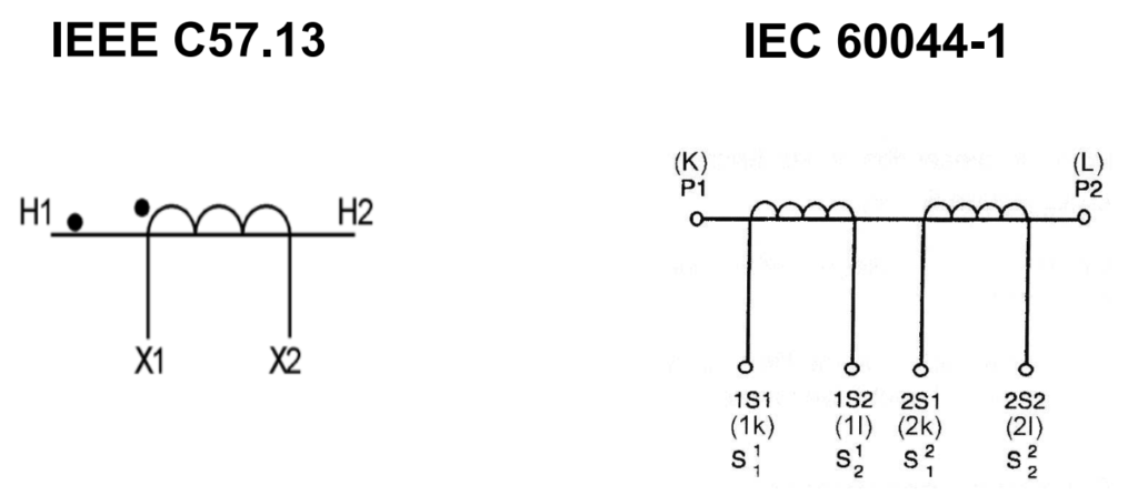
Current Transformer Secondary Types
Current transformer (CT) secondary types refer to the standardized current ratings used for the secondary winding of the CT. The secondary current rating is an important aspect of CT specification and is typically expressed in either 5 Amps or 1 Amp. The standards you mentioned, IEEE C57.13 and IEC 60044-1, provide guidelines for CT specifications.
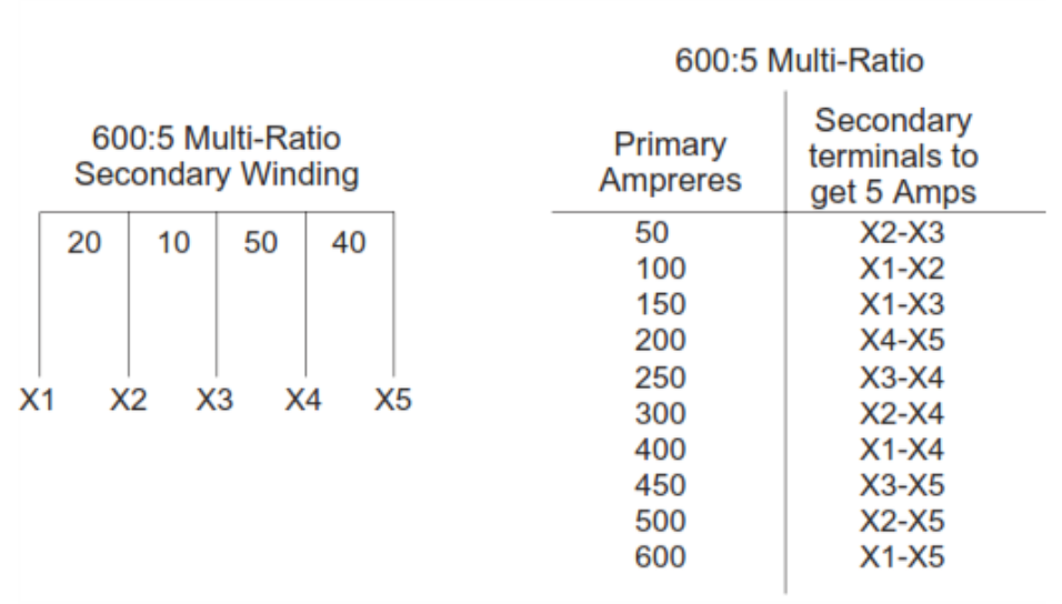
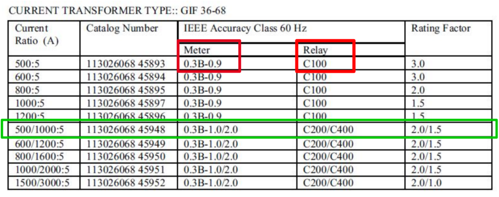
Multi Ratio Example:
CTs for Protection and Metering Applications
In current transformers (CTs), a big difference exists between metering class and protection class CTs, and this demarcation is particularly evident in the design of their magnetic cores. This differentiation ensures that each type performs optimally based on the specific requirements of the connected devices.
Metering cores are engineered to operate with precision within their designated current range. Their primary purpose lies in facilitating accurate measurements for billing, energy consumption monitoring, and other metering applications. When the current flow surpasses the rated range, the metering core undergoes saturation, strategically limiting the current level within the device.
This saturation acts as a protective mechanism, preventing connected metering devices from overloading during fault conditions. Furthermore, metering cores play a role in buffering the meter against experiencing excessive torques generated during faults, contributing to the overall longevity and reliability of metering equipment. Notably, metering cores offer high accuracy within a smaller current range, requiring less core material and resulting in lower saturation voltages.
On the other hand, protection cores serve a distinct purpose, specifically designed to transform a distortion-free signal even in the presence of high overcurrent conditions. Their primary function is to enable protective relays to accurately measure fault current values during fault scenarios. Unlike metering cores that become saturated to limit current, protection cores are engineered to work well into the overcurrent range.
This characteristic is essential for ensuring that protective relays can operate accurately in fault current scenarios. Given that relays are required to perform in fault current situations, protection cores provide moderate accuracy over a wider current range. This design necessitates more core material to handle the stresses associated with fault currents and maintain accuracy in a broader current spectrum.
The difference between metering and protection cores is pivotal, shaping their response to current levels and aligning with the specific needs of the connected devices. Metering cores prioritize high accuracy within a smaller range and provide saturation protection for metering devices. In contrast, protection cores are designed to accurately represent fault currents over a wider range, supporting the performance of protective relays in fault situations.
Protection CT Classes (IEEE C57.13)
IEEE C57.13-2008 defines specific classes to characterize their accuracy and performance under various conditions. One such class is denoted as “C200,” and it is associated with certain specifications and requirements outlined by the standard:
C200 Class:
- C Rating Criteria:
- Less than 3% Ratio Error at Rated Current: This criterion ensures that the CT maintains high accuracy at its rated current, with a permissible error of less than 3%.
- Less than 10% Ratio Error at 20 Times Rated Current: Even at 20 times the rated current, the CT is expected to provide accurate measurements, allowing for a slightly higher ratio error of less than 10%.
- Standard Burden: The standard burden is calculated as 200V divided by the product of 5A (rated current) and 20 (multiplier for 20 times rated current), resulting in 2 ohms.
- 200V/ (5A x 20) = 2Ω.
- In CTAnalyzer – This is known as Vb.
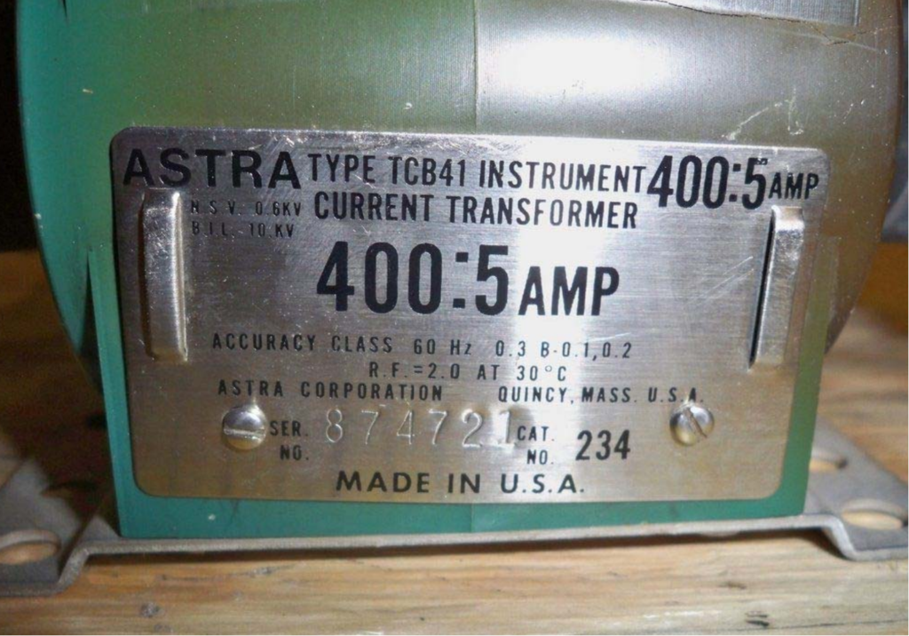
Actual Transformer Label (Protection Class)
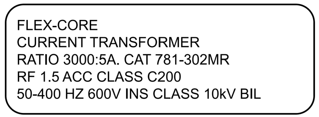
- Manufacturer’s name or trademark
- Manufacturer’s type
- Rated primary and secondary current
- Continuous thermal current rating factor (RF)
- Accuracy classes
- Rated frequency (Hz)
- Insulation and Basic impulse insulation level (BIL kV)
Other Protection CT Classes (IEEE C57.13)
In addition to the C200 class, IEEE C57.13 defines other protection current transformer (CT) classes, each with specific characteristics and performance criteria. Here are some additional protection CT classes outlined in the standard:
- C Class:
- Characteristics:
- Ratio Error Determination: The ratio error for the C class can be determined by calculation from the excitation curve. This allows for a theoretical assessment of the CT’s performance based on its excitation characteristics.
- Characteristics:
- K Class:
- Characteristics:
- Similar to C Class: The K class is similar to the C class, with the ratio error determined by calculation from the excitation curve.
- Additional Requirement: However, in the K class, the knee-point (a specific point on the saturation curve) must be greater than 70% of the Vb (secondary terminal voltage) rating. This ensures a certain level of performance under saturation conditions.
- Similar to C Class: The K class is similar to the C class, with the ratio error determined by calculation from the excitation curve.
- T Class:
- Characteristics:
- Ratio Error Determination: Unlike the C and K classes, the T class requires that the ratio error be determined by actual testing due to significant leakage flux. This involves experimental assessment to ensure accurate CT performance.
- PX Class:
- Characteristics:
- User-Defined Performance: The PX class allows for user-defined CT performance criteria. Users can specify parameters such as Vk (knee-point voltage), Ik (knee-point current), and Rct (CT resistance). This class provides flexibility for tailoring CT characteristics to specific application requirements.
- Characteristics:
Metering CT Classes (IEEE C57.13)
IEEE C57.13-2008 defines metering current transformer (CT) classes that specify the accuracy and performance characteristics of CTs used in metering applications. These classes help ensure precise and reliable measurement of current for billing, energy monitoring, and other metering purposes.
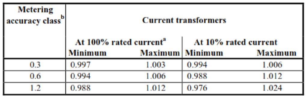
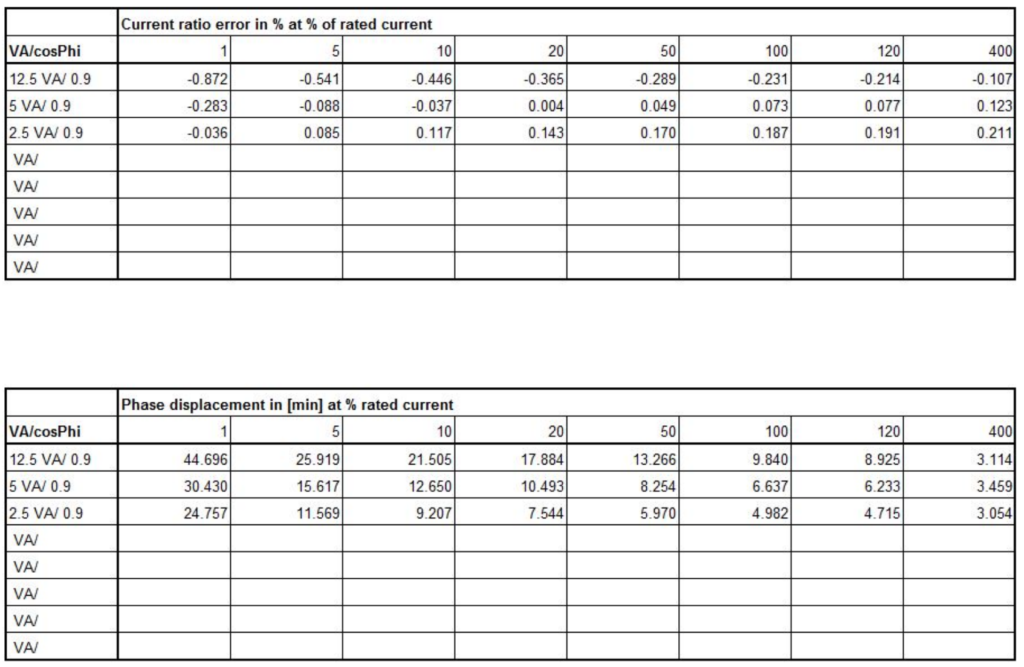
Ratio Error:
Rating Factor (RF)
The concept of “Multiples of Rated Current to which the CT can maintain its accuracy” is often referred to as the Rating Factor (RF). The Rating Factor indicates the maximum fault current that a current transformer (CT) can handle without exceeding specified limits on its accuracy. It is expressed as a multiple of the CT’s rated current.
In the example, with a 200/5A CT and an RF of 2, it means the CT can maintain its accuracy certification up to twice its rated current. Let’s break down the calculation:
Maximum Fault Current=RF×Rated Primary Current
For the given example:
Maximum Fault Current=2×200A=400A
Therefore, the CT will maintain its accuracy certification up to 400A. This implies that under fault conditions where the current is within this limit, the CT will operate accurately and reliably, adhering to its specified accuracy class.
Typical Rating Factors (RF) include values like 1, 1.5, 2, 3, and 4. These values represent the multiples of rated current up to which the CT can maintain accuracy. The choice of the RF depends on the application, system requirements, and the level of fault currents expected in the power system.
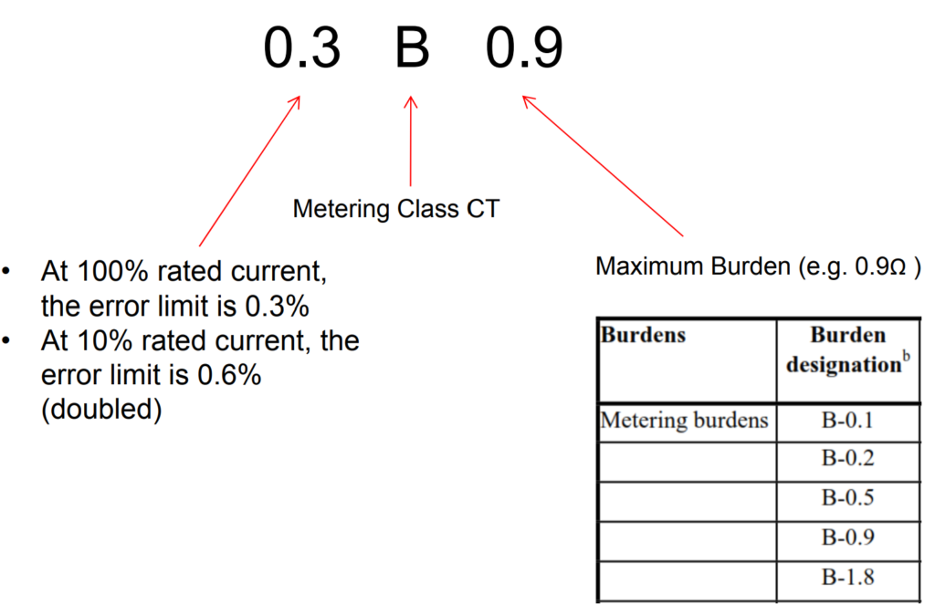
Metering CT Accuracy
Actual Transformer Label (Metering)
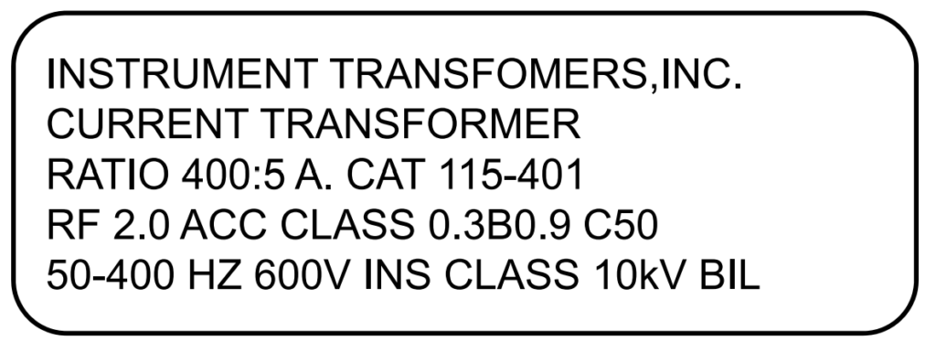
- Manufacturer’s name or trademark
- Manufacturer’s type
- Rated primary and secondary current
- Continuous thermal current rating factor (RF)
- Accuracy classes
- Rated frequency (Hz)
- Insulation and Basic impulse insulation level (BIL kV)
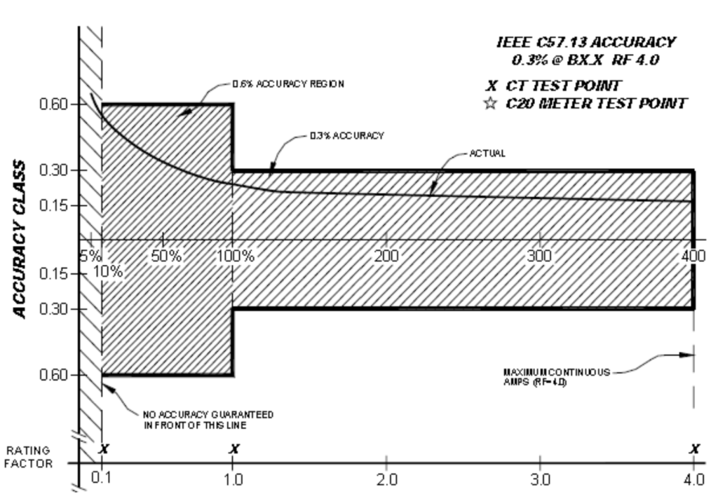
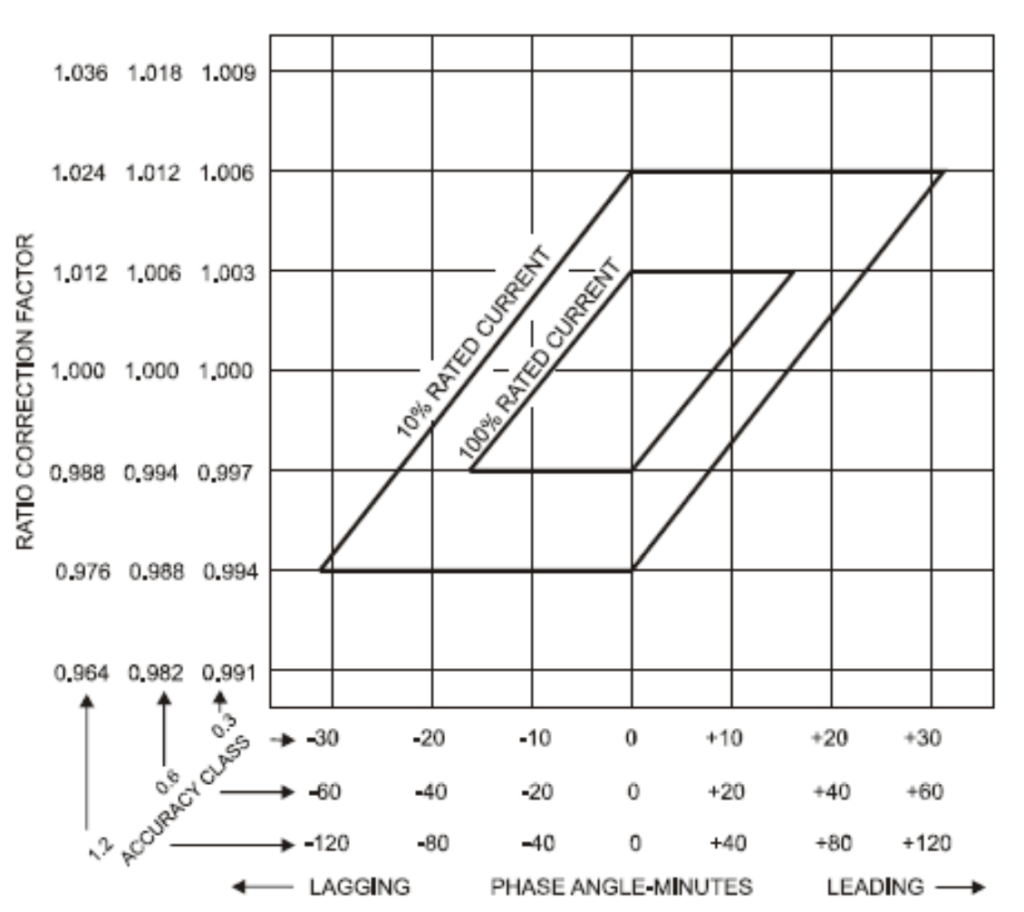
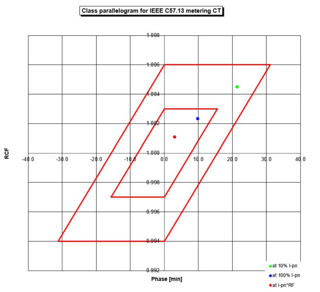
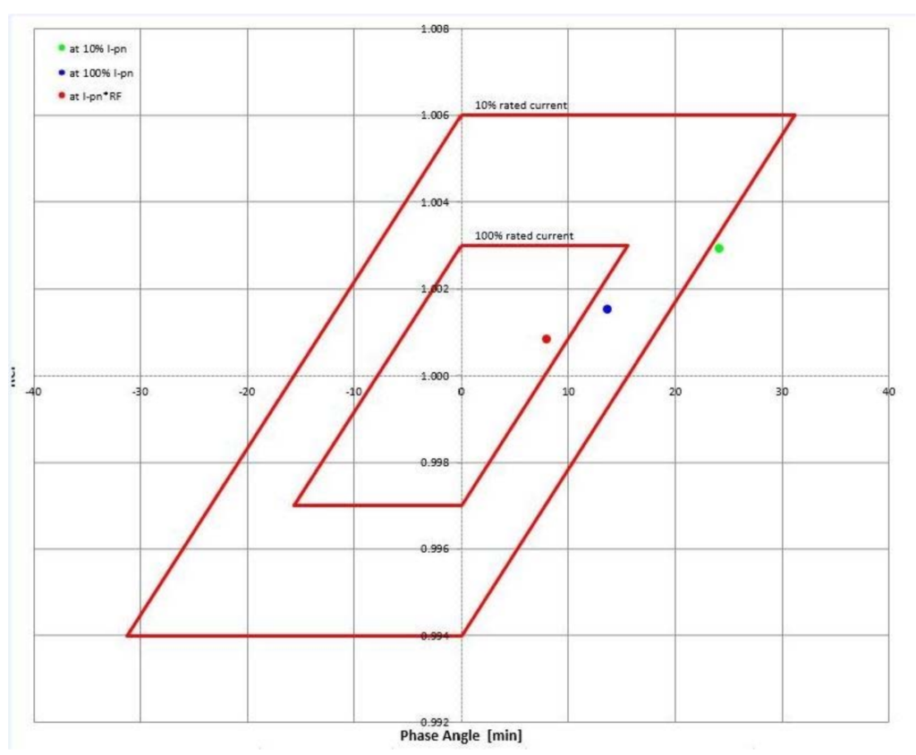
Error Parallelogram: Metering CTs
CT Selection
Selecting the right current transformer (CT) is a crucial step in ensuring accurate and reliable current measurement in power systems. Several factors should be considered when choosing a CT for a specific application. Here are key considerations for CT selection:
- Application Requirements:
- Accuracy Class:
- Burden and Load:
- Rated Primary and Secondary Currents:
- Rating Factor (RF):
- Saturation Characteristics:
- Environmental Conditions:
- Physical Size and Mounting:
- Standards Compliance:
- Budget Considerations:
- Vendor Reputation:
By carefully considering these factors, engineers and system designers can select current transformers that meet the specific needs of their power systems, ensuring accurate measurement and reliable operation in various conditions.
Residual Magnetism (Remanence flux)
When an external magnetic field, typically generated by the flow of primary current in the CT, is applied to the core, the magnetic domains within the core align themselves. This alignment results in the creation of a magnetic flux within the core.
When the excitation (external magnetic field) is removed, some of the magnetic domains within the core retain a degree of alignment or orientation relative to the original magnetic field that was applied. This residual alignment of magnetic domains leads to the presence of residual magnetism in the core.
In the current transformers, the amount of flux left in the core due to residual magnetism is crucial because it can impact the accuracy and performance of the CT. Residual magnetism can cause the core to be partially saturated, affecting the linearity of the CT’s response and introducing errors in the measurement of secondary current, particularly during low-current conditions.
Causes of Residual Magnetism
The causes of residual magnetism such as electrical devices like transformers or current transformers, can indeed be due to specific operational or testing conditions. Here are some causes of residual magnetism in electrical systems:
- High Transient Fault Currents:
- During transient fault conditions, where there is a sudden and temporary increase in current in the system, the magnetic fields generated can lead to residual magnetism in ferromagnetic components, such as transformer cores or current transformer cores.
- Circuit Breaker Arc During Trip Operations:
- The operation of circuit breakers involves the interruption of current flow. The arc formed during the trip operation can induce magnetic effects in the surrounding materials, potentially leading to residual magnetism in the circuit breaker components.
- DC Currents Due to Winding Resistance Measurement:
- When measuring the winding resistance of transformers or other devices using DC currents, the application of a direct current can induce magnetic effects in the core material. Subsequent demagnetization procedures are often necessary to minimize residual magnetism.
- Other Tests:
- Certain diagnostic or testing procedures, especially those involving magnetic fields, may introduce residual magnetism. This can occur during various tests, including insulation resistance tests, partial discharge tests, or other tests that involve the application of magnetic fields.
Residual Magnetism – How to get rid of?
Getting rid of residual magnetism is crucial in applications where accurate magnetization and demagnetization are essential for proper operation. Here are common methods to eliminate or reduce residual magnetism:
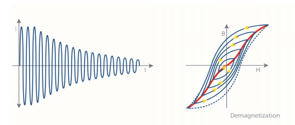
- Demagnetization Using AC Current.
- Saturation and Demagnetization.
- Decreasing the Magnetic Field Gradually.
- Hammering or Mechanical Shock.
- Heat Treatment.
- Reverse Magnetization.
- Using a Demagnetizing Coil.
- Specialized Demagnetization Equipment.
Done automatically by the CT Analyzer at the very end of the measurement.
Test Methods
- Primary Injection
- Secondary Injection – Fixed Frequency
- Secondary Injection – Variable Frequency.
Current Transformer Test Requirements
- Excitation to Determine Knee/Saturation Point
- Insulation
- Polarity
- Winding Resistance
- Primary Ratio
- Secondary Ratio
- Burden Check.
Why So Many Tests are required for Current Transformer?
- Ensure proper Relay Operation
- Certify Billing Accuracy
- Reduce Possibility of Failure when Energized
- Reduce Possibility of Injury Due to Failure
- Manufacturing Defects Do Happen
- Installation Errors Do Happen
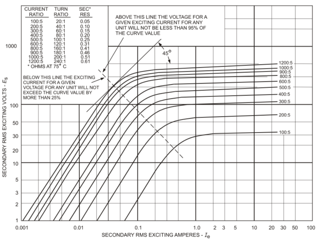
Excitation curves for multi-ratio C class CT
Relay Class Test Result
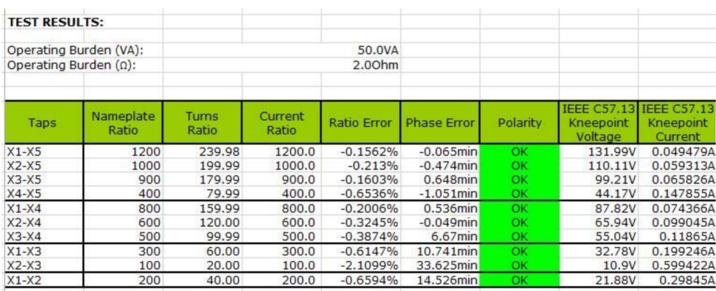
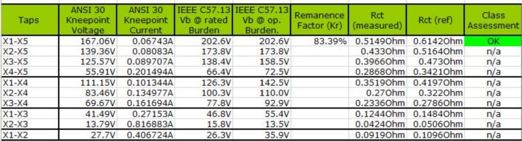
Test Results
Actual Test Results – Pass
Actual Test Results – Failure
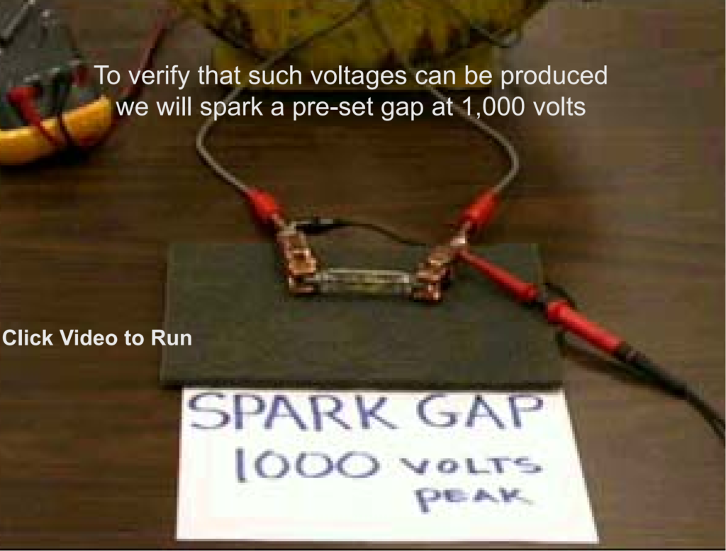
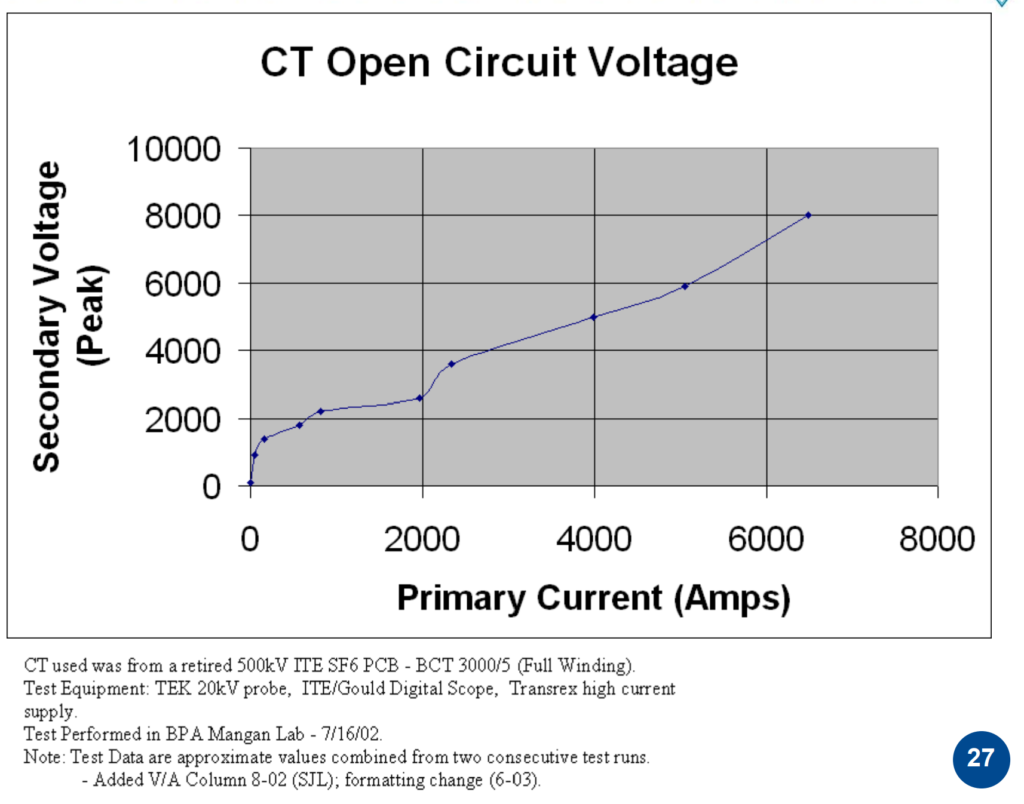
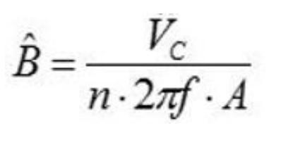
CT as a Voltage Transformer
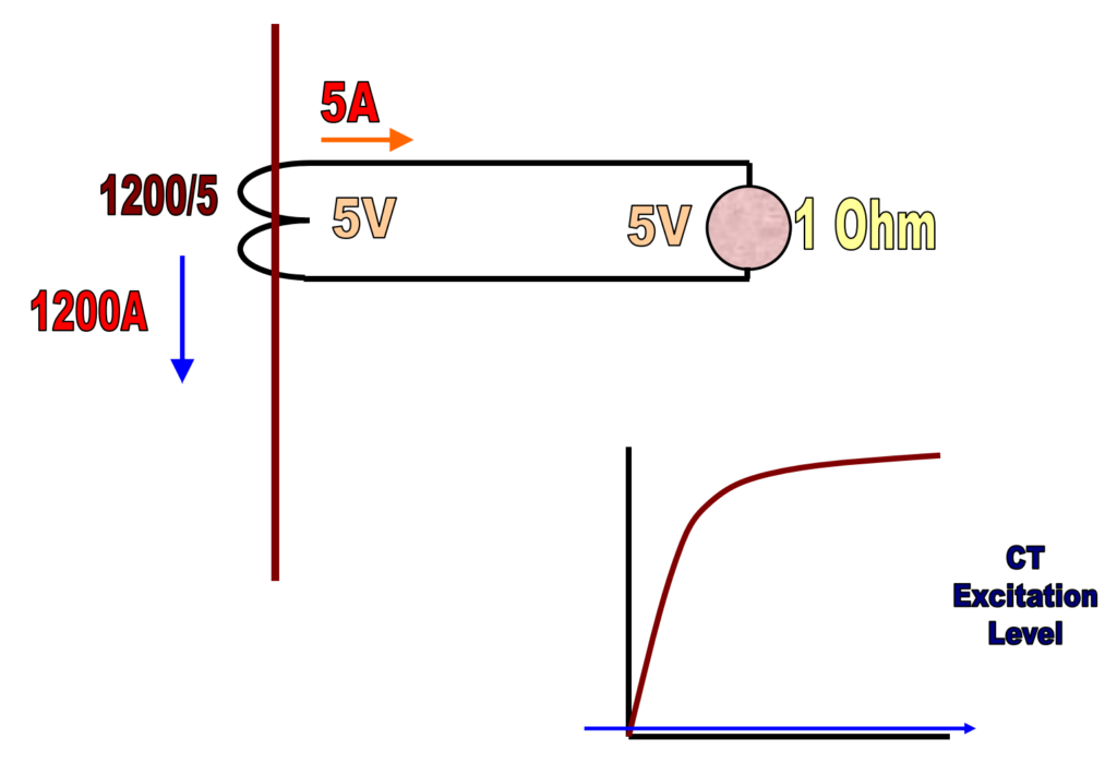
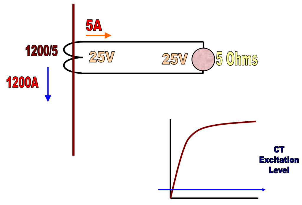
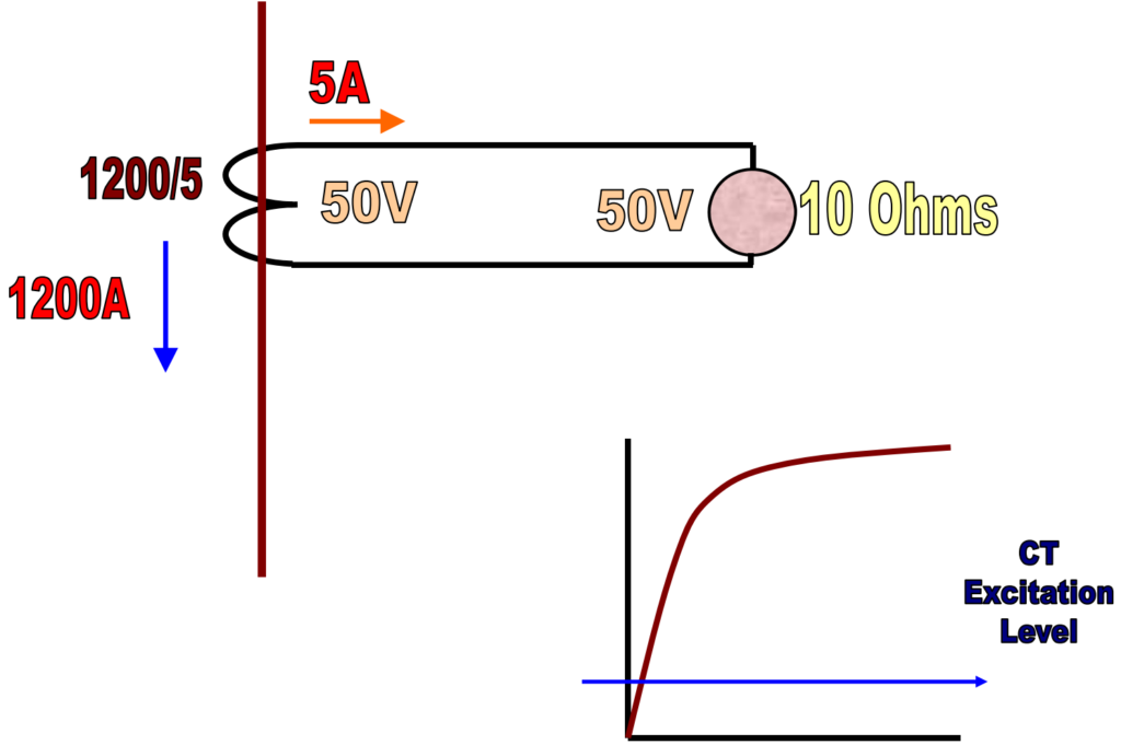
CT with varying burden
In electrical systems, the burden of a current transformer (CT) refers to the impedance presented to the secondary winding of the CT. The burden includes the resistance, inductance, and capacitance of the connected devices such as relays, meters, or other instruments. When the burden on a CT varies, it can impact the accuracy and performance of the CT, and understanding this variation is crucial for proper operation.
Single CT’s
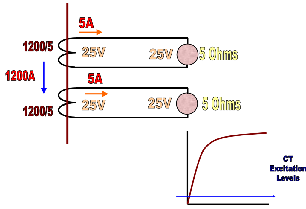
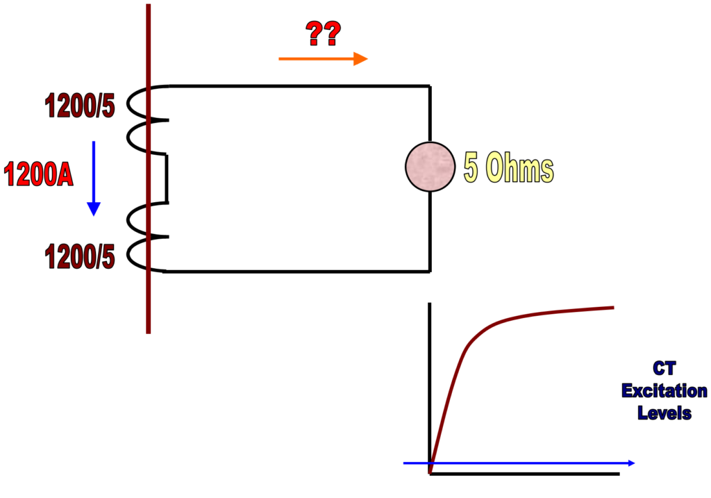
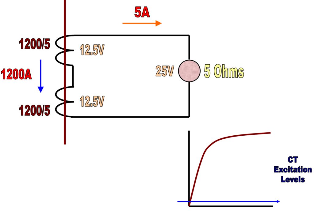
CT’s in Series
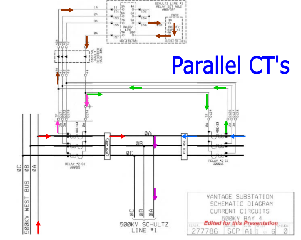
CT’s in Parallel
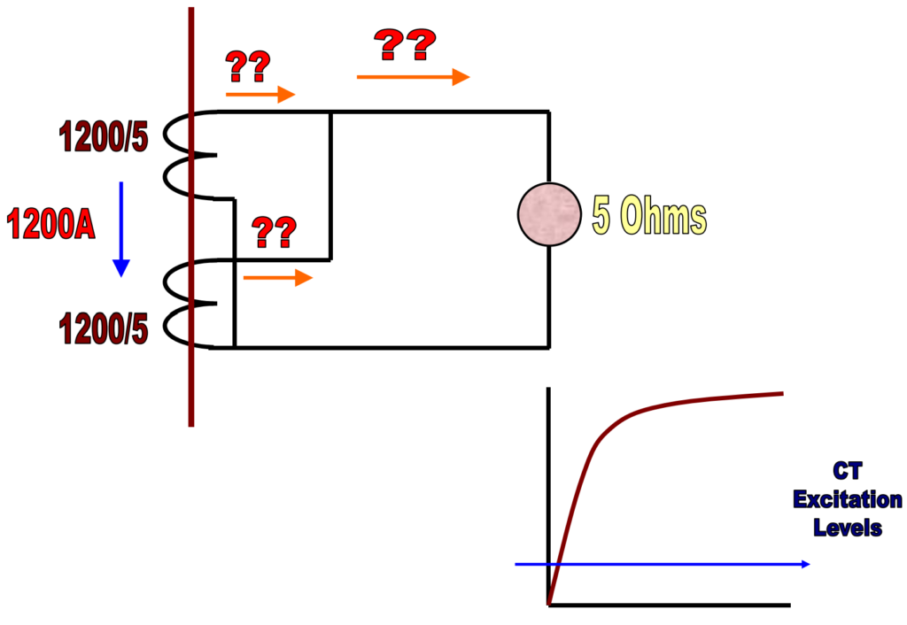
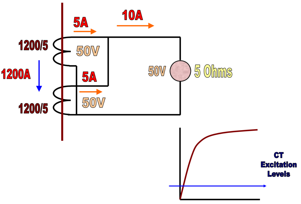
- As the secondary burden increases the transformer excitation voltage also increases above the normal level.
- If the secondary burden increases enough, the core will saturate.
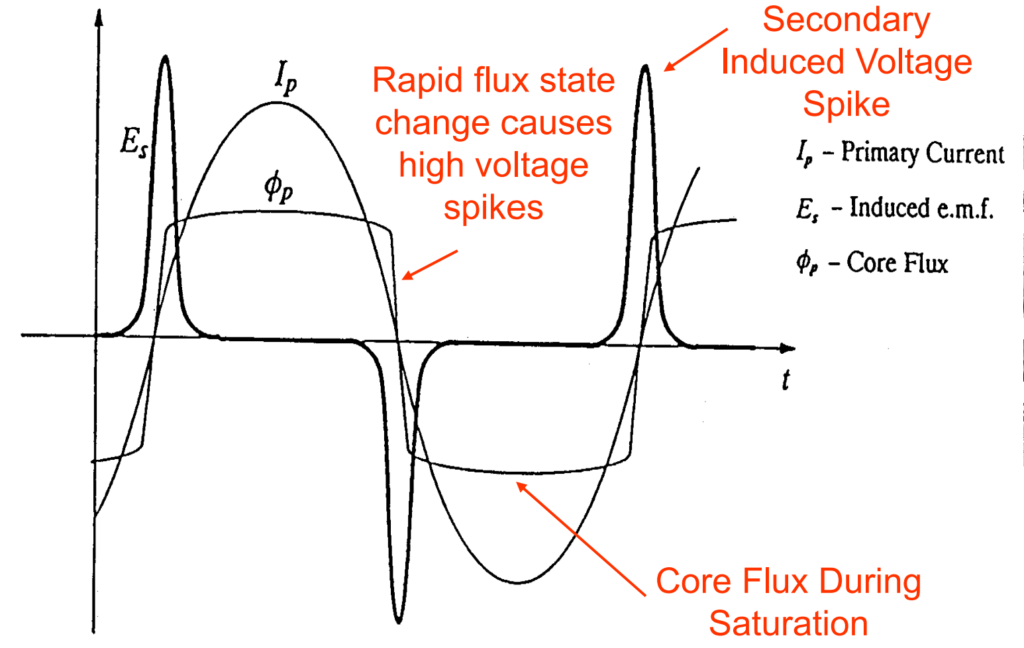
Secondary open circuit wave shapes
CT’s with large inductance and a high number of turns produce the highest open-circuit secondary voltages.