This article is for selection of metallic pipe flanges, Various types of flanges and provides information on pressure temperature ratings, dimensions, tolerances, materials, marking, and testing of flanges and flanged fittings in sizes NPS 1/2 to 60, and classes 150 to 2500.
This Article shall be used in conjunction with ASME B16.5, B16.47, B31.1, B31.3, B31.4, and B31.8. In case of conflict between the requirements specified herein and those stipulated elsewhere in other international standards; the most stringent requirements shall be adopted after obtaining approval by company.
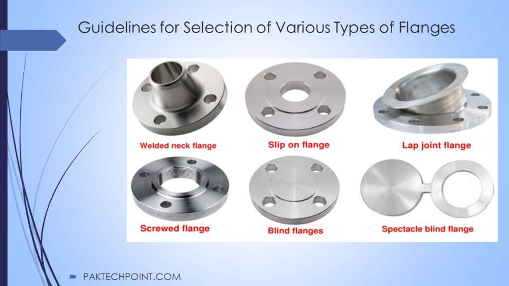
3. Guidelines for Selection of Various Types of Flanges With Design Limitations
3. Selection of Various Types of Flanges
3.1. Pressure Temperature Rating
3.1.1. Ratings for the applicable materials listed in ASME B16.5, Table 1A shall be the maximum allowable working gage pressures at temperatures shown in Table 2 of the same standard.
The basis for establishing ratings shall be the minimum wall thickness, which shall be in
accordance with ASME B16.5, Annexure B . The material groupings are based on closely
matched allowable and yield strength values.
3.1.2. Within each pressure class, the dimensions are held constant, irrespective of the material. Physical properties, and thereby the allowable stress values, of different materials vary, so the pressure temperature ratings within each pressure class vary with the material. For example, a class 600 forged carbon steel (A 105) flange is rated at 1265 psig at 400 F, whereas a class 600 forged stainless steel (A182-F304) flange is rated at 995 psig at 400 F.
3.2. Flange Dimensional Standards
3.2.1. The following dimensional standards shall apply to metallic flanges, and bolt hole patterns of nonmetallic companion flanges:
a. ASME B16.1, for integral cast iron flanges and blind flanges.
b. ASME B16.5, Classes 150, 300, 600, 900, 1500 up to NPS 24 and class 2500 up to NPS 12. Class 400 carbon steel flanges shall not be used.
c. Flanges larger than NPS 24 shall be specified in accordance with ASME B16.47, series B in class 150 to 900.
d. Flanges of unlisted materials and flanges not covered by the above standards shall be designed in accordance with ASME Section VIII Div 1, Appendix 2, and for blind flanges, in accordance with ASME Section VIII Div 1, Section UG-34.
3.2.2. Tolerances for flanges shall be in accordance with ASME B16.5, section 7 for flanges up to NPS 24, and ASME B16.47 Series B for flanges over NPS 24.
3.3. Flange Facings
3.3.1. Dimensions for facings shall be in accordance with ASME B16.5, Table 4 for flat face, raised face, and tongue and groove flanges, and Table 5 for ring joint flanges. These tables shall be used in conjunction with ASME B16.5, Figure 7.
3.3.2. Flat face flanges, with full-face gaskets, shall be used when one or both of the mating flanges in a joint are ASME B16.1. Class 125 gray cast iron, aluminum, or plastic, can be overstressed by bearing against a raised face. Adapter rings may be necessary in some cases, to level off the surface, for mating equipment.
3.3.3. Classes 150 and 300 pipe flanges and companion flanges of fittings are regularly furnished with 2 mm (0.06 inch) raised face, which is in addition to the minimum flange thickness(t) . Classes 400,600,900,1500 and 2500 pipe flanges and companion flanges of fittings are regularly furnished with 7 mm (0.25 inch) raised face, which is in addition to the minimum flange thickness(tf).
3.3.4. In ring joint flanges, thickness of lap remaining after machining the ring groove shall not be less than the nominal wall thickness of the pipe used. Ring joint flanges for use with ASME B16.20 ring joint gaskets shall be used for:
a. Flanges in Class 900 and higher ratings.
b. Design temperatures in excess of 480 C.
c. Hazardous fluid mediums.
3.3.5. Tongue-and-groove facing, and male-and-female facing joints, shall not be used except in high-pressure service, or when it is necessary to match existing equipment.
3.3.6. Flanges shall be finished in accordance with MSS SP-6, and ASME B46.1. Table I provides acceptable ranges of contact surface finishes for each type of gasket and service. The surface finishes shall be in Ra, Roughness average, expressed in micrometers, followed by micro-inches.
3.3.7. Flange roughness shall be judged by visual comparison to Ra standards using GAR model S22 Micro Finish Comparator or approved equal.
3.3.8. Ring joint flanges shall have flat-bottom type grooves in accordance with ASME B16.20.
3.4. Jack Screws
See Table II for Jack Screw diameter and length.
3.4.1. Jackscrews shall be used to facilitate flange separation for maintenance. Joint assemblies that often require frequent separation include orifice plates, spectacle plates, spacers, screens, and dropout spools.
3.4.2. Piping layout shall be designed in a way that flanges can be separated without excessive force.
3.4.3. Jackscrews shall be installed to be accessible from both sides of the pipe.
3.4.4. For orifice flanges, jackscrews shall be installed at 3 and 9 o’clock positions.
3.4.5. Jackscrews shall be specified in inch sizes, to match with the inch-sized flange bolt holes and bolting.
3.4.6. When flange separators are used, the use of jackscrews shall be optional.
3.5. Bore of Welding Neck Flanges and Hub Design
3.5.1. Dimensions of welding ends, bevel slopes and bores shall be in accordance with ASME B 16.5, and Figures 8 to 14.
3.5.2. Mis-matches between pipe and flange shall be corrected during fabrication. Weldneck shall be taper bored, if specified in the purchase description. Pipe wall thickness shall be specified in the purchase description to ensure that the flange is bored within the specified tolerance.
3.6. Hardness
Minimum Hardness for metallic Ring joint type flanges shall be as follows:
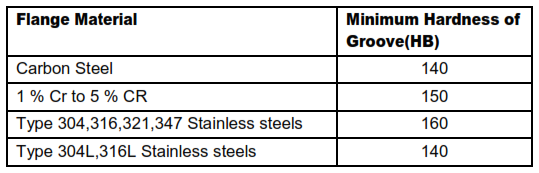
Difference of 30 to 50 BHN is to be maintained between flange and Gaskets.
4. Flange Material Limitations
4.1. General
4.1.1. Flanges and flanged fittings shall be forgings, or plates. Use of flanges in cast construction shall be limited to body flanges of valves, Strainers, Pump casings and such other equipments only. Flanges in cast construction shall not be used as piping counter flanges.
4.1.2. Minimum material requirements shall conform to respective PIPs, listed in SES P02-S01, P02-S14, P03-S01, P04-S01 & Table-III.
4.1.3. Bolting materials shall conform to ASME B16.5, Table 1B.
4.1.4. The material for flanges in pipeline service shall be suitable for welding. The carbon
equivalents shall match the pipe material.
4.1.5. The requirements in 4.2 to 4.8 supplement PIP material specifications where PIP
requirements are inadequate.
4.1.6. Flanges requiring galvanizing shall be Zinc coated using hot dip galvanizing process
conforming to ASTM A 153. Flange facing shall be protected suitably during galvanizing in
order to avoid irregular surfaces which will lead to leakage when flanges are assembled.
4.2. Iron Flanges
4.2.1. Cast Iron Flanges: Gray cast iron flanges shall not be used for process piping within the
battery limits of any plant. The only exception shall be for use in approved fire systems. The
material shall be ASTM A 126, Class B.
4.2.2. Ductile Iron Flanges: Ductile iron flanges may be used, in proprietary systems, for example plastic lined steel piping, as back-up flanges for lapped joints.
4.2.3. ASME B16.1 Class 125 and class 250 cast iron flanges may be mated with ASME B 16.5
class 150 and 300 steel flanges respectively. However care shall be exercised to ensure that
a flat-faced cast iron flange shall mate only with a flat faced steel flange, and vice versa.
4.3. Carbon Steel Flanges
Carbon steel flanges shall not be used in services over 425 C.
4.3.1. General Service: Standard carbon steel material shall be ASTM A 105. Standard material shall be used between minus 29 C and 425 C. Company may specify additional requirements, for example normalizing. These special requirements shall be added to the purchase description.
4.3.2. Low-temperature Carbon steel flanges used for services from minus 29 C to -45 Deg C, shall conform to the impact-testing requirements of SES P02-S01. ASTM A 350-LF2 shall be the standard material for this service.
4.4. Low and Intermediate Alloy Steel Flanges
Material for Low alloy steel flanges (1 1/4 Cr -1/2 Mo) shall be ASTM A 182-F11. Material for intermediate alloy steel flanges ( 5 Cr – 1/2 Mo) shall be ASTM A 182-F5.
4.5. Stainless Steel and Non-ferrous Flanges
Flanges shall be in forged construction. When flange material is not forged, the material for flanges shall be subject to approval.
4.6. Pipeline Service Flanges
Flanges for pipeline service shall match SMYS, and carbon equivalency specified in
ASME B31.4 and B31.8.
4.7. NACE Service Flanges
When an in plant service has water and HS concentrations above the limits specified in NACE MR0175/ISO 15156, that service shall be considered as NACE service. Flanges for use in NACE service shall be in accordance with NACE MR0175/ISO 15156 special requirements. Purchase description shall specify ‘NACE service’.
4.8. High Strength Material Flanges for Pipeline Service High strength material are fittings for API Std. 5L pipe Grade X42 to X65.
5. Flange Types
Selection of appropriate joining methods varies with the required mechanical strength in the joint, from a minimum, as in slip-on connections, to maximum, as in integral-type flanges that are cast, integrally forged or butt-welded to the pipe.
5.1. Weldneck Flanges
5.1.1. ASME B16.25 weld neck flanges with tapered hub and welding end shall be the primary selection for flanged joints in metallic piping systems of NPS 2 and larger. The individual material classes show the size range for any given service.
5.1.2. Weld neck flanges shall be used in piping line classes for service such as steam, process hydrocarbon and corrosive services .
5.2. Threaded Flanges
5.2.1. When new material classes are generated threaded flanges shall be added to material classes for threaded service, generally for mating equipment, and transitions between threaded and flanged piping.
5.2.2. Threaded flanges may also be used for Potable water and Instrument air service in pipe sizes NPS 3 and less and at design temperature of 250 F and below. Seal welding shall not be required.
5.2.3. Threaded flanges shall have taper type threads and shall conform to ASME B1.20.1.
5.3. Socket weld Flanges
Socket weld flanges and socket weld reducing flanges are added to material classes for pipe
sizes 11/2” & below.
5.4. Slip-on Flanges
5.4.1. Slip-on flanges cost less than welding neck flanges, and require less accurate pipe cutting, but their strength is approximately 2/3 of weldneck flanges under internal pressure, and they have approximately 1/3 the fatigue life of weldneck flanges.
5.4.2. Slip-on flanges shall be welded at the front and back of the hub, but not on the sealing face.
5.4.3. Slip-on flanges and reducing slip-on flanges shall be limited to Category-D fluid service only. However, slip-on flanges shall not be used in the following services:
a. Severe cyclic conditions. See ASME B31.3, paragraph 300.2.
b. Design temperatures above 230 C, or where the corrosion allowance exceeds 3 mm.
c. ASME B16.5 Class 300 or higher rating.
d. Flange sizes larger than NPS 24, unless stress calculations in accordance with ASME Section VIII Div 1, Appendix 2, with thermal and other external piping loads considered, show that the slip-on flanged joint will not be over-stressed.
e. Piping subjected to vibrations.
5.5. Lapped Joint Flanges
5.5.1. A lap joint is made up of a pair of stub ends, a pair of lap joint flanges, bolts and gaskets. These allow easy alignment of bolt holes and flanged joints.
5.5.2. See SES P16-G01 for stub-ends. The stub end shall match the material of the pipe. Stub ends for lapped joint flanges, if fabricated by welding, shall be made with full penetration welds.
5.5.3. Advantages are that lapped joints are an economical alternative to weld necks, and costs savings are large when the material is very expensive; dissimilar materials can be joined,
provided galvanic corrosion does not occur.
5.5.4. The disadvantage of this joint is that it is sensitive to external stress. Lapped joint flanges shall not be used in severe cyclic conditions, low temperature and in cryogenic services.
5.6. Blind Flanges
5.6.1. Blind flanges shall be used as end closures on flanged ends and valves, unless end caps are specified in design.
5.6.2. Blind flanges are forgings, and shall be manufactured to the same materials standards as other matching flanges.
5.6.3. Blind flanges shall be of the same material as the Weldnecks, in all services. In corrosive atmospheres, stainless steel Blind flanges shall be used.
5.6.4. Blind flanges shall not be drilled for connections, for example drains and flushing, unless stress calculations in accordance with ASME Section VIII Div 1, Appendix 2 show that the flanges will not be over stressed.
5.7. Orifice Flanges
5.7.1. Orifice flanges shall conform to this standard and ASME B16.36.
5.7.2. Orifice flanges shall be weld neck flanges.
5.7.3. Orifice flanges shall have jackscrews to facilitate disassembly of the flanged joint during maintenance.
5.8. Other Standards
Other standards, for example AWWA C207 for hub flanges, may be required for proper
mating to equipment, and shall be reviewed at the time of generation of a material class.
6. Bolts and Gaskets
For design and material requirements see Selection of Bolts and Selection of Gaskets respectively.
7. Purchase Description
Refer for Purchase specification for Pipe, fittings and flanges. The following shall be included in the purchase description for flanges:
a. Type of flange
b. Nominal size of flange
c. Rating
d. Wall thickness as defined by schedule, weight or actual decimal wall
e. Dimensional standard
f. Flange facing
g. Contact surface finish
h. Material grade
i. Tolerances
j. Additional material testing requirements, if applicable
8. Marking
Flanges and flanged fittings shall be marked in accordance with MSS SP-25. The following shall be included in the marking:
a. Pressure rating class
b. ASME B16 designation
c. Nominal pipe size
d. The letter ‘R’ and the corresponding ring groove number for ring joint flanges
e. Material grade of flange
f. Type of flange facing
g. Schedule or wall thickness for weld-neck flanges.
2. References
Reference is made in this article to the following documents. The latest issues, amendments, and supplements to these documents shall apply unless otherwise indicated.
- Selection of Wrought Butt-weld Fittings.
- Selection of Gaskets.
- Selection of Bolts.
- Purchase specification for Pipe, fittings and flanges.
5. American Society for Testing and Materials (ASTM)
- ASTM A 105 -Specification for Carbon Steel Forgings for Piping Applications.
- ASTM A 126 – Specification for Gray Iron Castings for Valves, Flanges, and Pipe Fittings.
- ASTM A 153 – Specification for Zinc coating (Hot-Dip) on Iron and steel Hardware.
- ASTM A 182 – Specification for Forged or Rolled Alloy-Steel Pipe Flanges, Forged Fittings, and Valves, and Parts for High Temperature Service.
- ASTM A 350 – Specification for Carbon and Low-Alloy Steel Forgings requiring Notch Toughness Testing for Piping Components.
6. American Society of Mechanical Engineers (ASME)
- ASME Boiler and Pressure Vessel Code Section VIII Div 1, Appendix 2, Section UG-34.
- ASME B1.20.1 Pipe Threads, General Purpose (Inches).
- ASME B16.1 Cast Iron Pipe Flanges and Flanged Fittings.
- ASME B16.5 Pipe Flanges and Flanged Fittings.
- ASME B16.20 Metallic Gaskets for Pipe Flanges – Ring Joint, Spiral-wound, and Jacketed.
- ASME B16.21 Non-Metallic Flat Gaskets for Pipe Flanges.
- ASME B16.25 Buttwelding Ends.
- ASME B16.36 Orifice Flanges.
- ASME B16.47 Large Diameter Steel Flanges.
- ASME B 31.1 Power Piping.
- ASME B31.3 Process Piping.
- ASME B31.4 Pipeline Transportation Systems for Liquid Hydrocarbons and Other Liquids
- ASME B31.8 Gas Transmission and Distribution Piping Systems
- ASME B46.1 Surface Texture(Surface Roughness, waviness and lay).
7. American Water Works Association (AWWA)
C207 Steel Pipe Flanges for Water Works Service.
8. Manufacturers Standardization Society (MSS)
SP-6 Standard Finishes for contact faces of pipe flanges and connecting end flanges of valves and fittings.
SP-25 Standard Marking System for Valves, Flanges, Fittings and Unions.
9. National Association of Corrosion Engineers (NACE)
MR0175/ISO 15156 Petroleum and Natural gas Industries-materials for use in H2S containing environments in oil and Gas production-Part 1 ,Part 2 and Part 3.
TABLE I Contact Surface Finish, TABLE II Jack Screws, TABLE III Services and Materials