This article is about Orifice Plate Material Selection Criteria Design for Flow Measurement of Instrumentation and Control Systems as per International Codes and standards for Commercial Buildings, Plants and Refinery Projects.
Orifice Plate Material Selection Criteria Design – Flow Measurement
Material Receiving General Checklist for Instrumentation & Control
General Requirements
- Purchase Order and Instrument specification sheet criteria shall be confirmed and compared with instrument stainless steel tags / labels and nameplates, and shipment checked for damage, prior to acceptance of the shipment
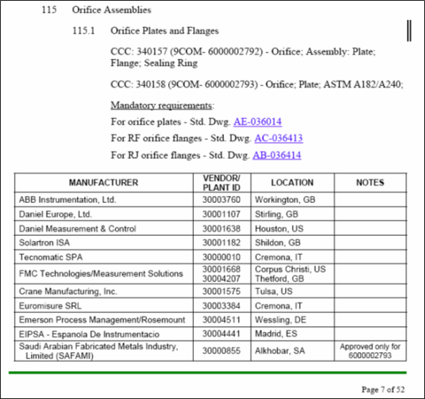
- Verify that all the instruments are from technically acceptable vendors, Attachment 1.
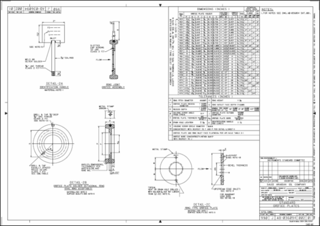
- Material for the orifice plate shall be ASTM A 240 TYPE 316 stainless steel, annealed condition with maximum hardness 217HB unless otherwise specified on the purchase order (See Attachment 2 “Std. Dwg. AB-036094 Sh 1 of 2, note 1” Standard Orifice Plates).
- Orifice plate handle and screws shall be a 300- series stainless steel or for severely corrosive service, obtain a material recommendation from Consulting Services Department (See Attachment 2″ Std. Dwg. AB-036094 Sh 1 of 2, note 1″ Standard Orifice Plates).
- Material for the plate holder shall be soft iron or low carbon steel with a maximum hardness of 120 HB (See Attachment 2″ Std. Dwg. AB-036094 Sh 1 of 2, note 2″ Standard Orifice Plates).
- Stainless steel orifice plate holders should be used with stainless steel flanges, to insure they are softer than mating flanges. Stainless steel holders shall have a maximum hardness of 150 HB unless otherwise specified in the order (See Attachment 2″ Std. Dwg. AB-036094 Sh 1 of 2, note 2″ Standard Orifice Plates).
- The surface quality of orifice plate inlet and outlet faces shall have a surface roughness rating equal to or finer than 50 micro inches( hone, lap, polish or buff finish) and shall be entirely free from surface defects (See Attachment 2″ Std. Dwg. AB-036094 Sh 1 of 2, note 3 ” Standard Orifice Plates).
- The surface quality of the orifice plate holder contacting the orifice plate shall have a quality equal to that required for orifice faces as above in item B7 (See Attachment 2″ Std. Dwg. AB-036094 Sh 1 of 2, note 3″ Standard Orifice Plates).
- For square edge orifice plates, the upstream edge of the orifice must be square and sharp, without defects of any sort, so that a beam of light is not reflected by the upstream edge when viewed without magnification (See Attachment 2″ Std. Dwg. AB-036094 Sh 1 of 2, note 4″ Standard Orifice Plates).
- The following items be metal stamped on the upstream side of the paddle type orifice plate handle or ring joint identification handle. For example: A) Tag : FE-480-100
B) Reference bore : dr 2.313″”
C) Line size : 6″”
D) ANSI OR API Flange rating : 150# ANSI E) Plate material : 316 SS
(See Attachment 2″” Std. Dwg. AB-036094 Sh 1 of 2, note 5″” Standard Orifice Plates)” - Verify calculated orifice bore “dc”, vent or drain hole “w” and thickness at throat “r” with those given on Eng Form 3175, 3176, or 3177 (See Attachment 2″ Std. Dwg. AB-036094 Sh 1 of 2, note 6″ Standard Orifice Plates).
- The outside Orifice Plate Edges shall be de-burred. (See Attachment 2″ Std. Dwg. AB-036094 Sh 1 of 2, note 8″ Standard Orifice Plates)
- For Eccentric and segmental plates, the tolerances on standard drawing AB-036094 sheet 1 of 2 may be used except for shape and or / location of orifice bore. (See Attachment 2″ Std. Dwg. AB-036094 Sh 1 of 2, note 9″ Standard Orifice Plates)
- The surface of the plate bevel shall have no defects visible to the naked eye, such as grooves, ridges, pits or lumps.
(See Attachment 2″” Std. Dwg. AB-036094 Sh 1 of 2, note 10″” Standard Orifice Plates)” - The measured orifice bore diameter, dm, is defined as the mean (arithmetic average) of four or more evenly spaced diameter measurements. None of the four or more diameter measurements may vary from the mean value by more than the tolerances given in detail 1 of the standard drawing (See Attachment 2″ Std. Dwg. AB-036094 Sh 1 of 2, note 11″ Standard Orifice Plates).
- The Orifice plate temperature (Tm) should be noted at the time the bore diameter measurements are made (See Attachment 2″ Std. Dwg. AB-036094 Sh 1 of 2, note 11″ Standard Orifice Plates).
- It is also acceptable for the Orifice plate and handle to be manufactured as one piece (See Attachment 2″ Std. Dwg. AB-036094 Sh 1 of 2, note 12″ Standard Orifice Plates).
- It is also acceptable to tack weld the orifice holder handle to the ring gasket instead of drill and tapping (See Attachment 2″ Std. Dwg. AB-036094 Sh 1 of 2, note 13″ Standard Orifice Plates).
- The orifice plate bore diameter, (dr) , is defined as the calculated reference diameter at reference temperature (Tr) 68º F, and can be determined using the following equation, dr = dm[1 + α (Tr-Tm) ] where α = linear coefficient of thermal expansion (in/in-º F). For common metals, type 304 and 316 SS, α =9.25 X 10⁻⁶ ; monel α =7.95 X 10⁻⁶ ; carbon steel α =6.20 X 10⁻⁶ (See Attachment 2″ Std. Dwg. AB-036094 Sh 1 of 2, note 14″ Standard Orifice Plates).
- R-23 dimensions do not alloow manufacturing as a plate holder because the band between “F” and ring ID is only 0.184″, (not enough space for hold down screws). Rings R-23 & R-24 plate holder may alternatively be specified with steel snap ring to hold orifice in place. (See Attachment 2 “Std. Dwg. AB-036094 Sh 1 of 2, note 15” Standard Orifice Plates).
- The Orifice plate thickness (E) and its deflection tolerances are valid for differential pressures not exceeding 200 inches of water column (150 inches water column for non bevel 8 inch plates ). Plate thickness tolerances are: a) Line sizes 2″” thru 8″” , (+ 0.005 and – 0.010)
b) Line size ≥10″” the tolerances(+0.020 and – 0.015).
(See Attachment 2″” Std. Dwg. AB-036094 Sh 1 of 2, note 16 Standard Orifice Plates)” - In case of Natural Gas Fluids measurements, plate thickness (E) and its deflection tolerances are valid for operating temperature not exceeding 150ºF and differential pressures not exceeding 200 inches of water column. Plate thickness tolerances are: a) Line sizes 2″” through 8″” , (+ 0.005 and -0.010) b) Line size ≥10″” the tolerances (+0.020 and – 0.015).
(See Attachment 2″” Std. Dwg. AB-036094 Sh 1 of 2, note 16 Standard Orifice Plates)” - In cases other than those stated in item B21 and 22 above, the manufacturer should be contacted for specific orifice plate thickness (E) and its deflection tolerance (See Attachment 2 “Std. Dwg. AB-036094 Sh 1 of 2, note 16” Standard Orifice Plates)
International Standard and Codes for Instrumentation Accessories
- Turbine Meter Material Selection Criteria Design & Flow Measurement
- Pitot Tube Design Requirement in Process Industry
- SAES-J-002 – Technically Acceptable Instruments, June 2008
- SAES-J-003 – Instrumentation Basic Design, January 2008
- SAES-J-100 – Process Flow Metering, 05 April 2008
- Standard Drawing Orifice plates 990-J- AB-036094 Sheet 1& 2 of 2 rev 16
1. Attachment 1: Technically Acceptable Instruments – SAES-J-002, June 2008
2. Attachment 2: Standard Orifice Plates Std Dwg. AB 036094 Sht. 1 of 2

3. Attachment 3: Standard Orifice Plates Std Dwg. AB 036094 sh 2 of 2