1. Scope – This article covers the minimum requirements for the cabling and wiring of process control systems. It does not cover cabling and wiring related to communication and IT systems. Refer to SSITS for communication and IT systems cabling and wiring.
2. References
References are made in this article to the following documents.
Duct Bank for instrument Cable
D03-D05 Electrical Equipment Numbering System.
Grounding & Lightning Protection, Buildings & Structures.
Conduit System Installation Requirements.
Conduit Metallic, PVC Coated & Non Metallic.
Cable Tray Installation Requirements.
Underground Excavation and Installation of Conduits, Manholes and Cables.
Underground Duct Bank, Conduit, Manhole and Cable Installation.
F02-E01 Fire Protection Systems.
R01-E02 Hazardous Area Instrument Protection -Explosion Proof.
R01-E03 Hazardous Area Instrument Protection -Intrinsically Safe.
R01-E04 Hazardous Area Instrument Protection -Purge and Pressurized Enclosures.
R11-C02 Standard Installation Drawings-Instrumentation.
Control System Design Criteria.
X05-E02 Field Device Cabling to Junction Boxes.
X05-S01 Process Control Cables Specification.
X05-S02 Local Control Panel Specification.
X06-C01 Standard Installation Drawings-Control System.
International Society of Automation (ISA).
MC96.1 Temperature Measurement Thermocouples.
RP12.01.01 Definition and Information Pertaining to Electrical Equipment in Hazardous (Classified) Locations.
RP12.4 Pressurized Enclosures.
National Electric Manufacturer Association (NEMA).
250 Enclosures for Electrical Equipment (1000 Volts Maximum).
National Fire Protection Association (NFPA)
70 National Electrical Code (NEC)
496 Standard for Purged and Pressurized Enclosures for Electrical Equipment
Process Industry Practices
PCCEL001 Instrumentation Electrical Design Criteria
3. Definitions
AC Safety Ground. The conductor used to ground the non current-carrying metallic enclosure.
Attenuation. A measurement of the decrease in magnitude of power of a transmitted signal. The result is expressed in decibels and is usually used to express the total loss in an optical system.
Class 1 Circuit. A circuit complying with NEC Article 725, Part II.
Control Network. Ethernet network where process control data is handled among the controllers and workstations.
Control Network Cable. The fiber optic, UTP, and coaxial cables used to handle the control network communication between RIB/RR and the control room.
Data Link. Communication link between the field instrument/equipment to the control system’s communication module.
Homerun Cables. Multi pair or multi triad cables from the junction box to the terminal strips in an unclassified building.
Instrument Circuits. Cabling from instrument till marshalling cabinet or panels.
Instrument Ground. The zero potential reference for the instrument signals.
Process Seal (NFPA70). The device that prevents mitigation of process fluid from the designed containment into the external electrical system.
Remote Instrument Building. A building at the site that contains the control system’s equipment.
Abbreviations and Acronyms
CR – Control room
RIB – Remote Instrument Building
RR – Rack room
SSITS – Shared Services IT Standards
4. Process Control Cabling Installation in Hazardous Area
4.1. General
4.1.1. All installations for instruments, devices, junction boxes, raceways, etc. shall be engineered to meet the area classification in which they are installed, per NFPA 70 and ISA RP12.01.01. They shall be accordingly certified for the classified areas in which they are installed.
4.2. Prevention of Liquid, Gases and Vapor Passage
4.2.1. Vapor and gas sealing of conduit and cables shall be provided. This is to minimize the passage of gases and vapors and prevent the passage of flames from one portion of the electrical installation to another through the conduit.
4.2.2. Conduit and cable sealing shall be in accordance with NFPA 70.
4.2.3. As a minimum the following design steps shall be used:
a. The junction box or enclosure in the classified location that terminates the cable or conduit leaving the classified area shall be vented to atmosphere.
b. Where feasible, these junction boxes shall be installed in non corrosive locations. If the enclosure is installed in a location where corrosive gases may be present, the enclosure shall be purged with instrument air.
c. The purge rate, 10 cc/min nominal, and vent size should preclude the possibility of pressure buildup in the enclosure. This purge is for reducing the corrosive gas concentration in the enclosure and should not be confused with purging requirements for hazard reduction as per NFPA 496.
d. Where environmental conditions include hose down practices or splashing water, breathers and drains shall not be used, and the cable ends shall be sealed to reduce the possibility of gases and vapors passing from the classified area to the non classified area.
e. The unclassified building or enclosure terminating the homerun cable shall have positive pressure/ventilation system.
f. All instruments connected directly to the flammable or combustible process shall be designed with additional process barrier, seal, or other means to prevent entry of the process into the cable / conduit system. The design shall be approved. Drains, vents, and other devices shall be provided to obtain indication of failure of primary seal as per NFPA 70. Refer to SES-R01-E02 for recommendations on barriers.
g. Cables entering pressurized buildings and enclosures shall be sealed for all openings to prevent air loss.
4.3. Purged Enclosures
4.3.1. Purge and pressurizing shall be in accordance with the requirements of NFPA 496 and ISARP12.4. Refer to SES-R01-E02 and SES-R01-E04 for purged and pressurized enclosures. Use of purging to reduce area classification shall be approved by SABIC.
4.4. Intrinsically Safe (IS)
4.4.1. Intrinsically safe circuits shall only be used when the area classification cannot be met by using the explosion proof and purge methods.
4.4.2. Usage of intrinsically safe wiring shall require SABIC approval.
4.4.3. Refer to SES-R01-E03 for intrinsically safe instrument systems.
5. Grounding
5.1. General
5.1.1. Grounding systems shall meet the requirements of PIP PCCEL001.
5.1.2. In the buildings the grounding bus-bars shall be installed under the elevated floor.
5.1.3. Green insulated copper wire shall be used for ac safety ground.
5.1.4. Green/yellow insulated copper wire shall be used for instrument ground.
5.1.5. AC safety ground bus shall be directly connected to the equipment cabinets.
5.1.6. All cabinets shall have an ac safety ground bar. If instrument ground is also required in cabinets, an isolated instrument ground bar shall be provided.
5.1.7. The ground bars shall be installed at the bottom and be suitably drilled and tapped for screw terminals and wire lugs. A number 8 AWG (10 mm2) screw type compression lug shall be provided on either end of each ground bar for connection to respective ac safety and instrument common ground bars.
5.1.8. Grounding resistance shall be proved by test and subject to inspection.
5.1.9. Grounding of signal circuits shall be at one point only, at cabinets’ location.
5.1.10. If applicable, refer to SES-R01-E03 for IS grounding specifications.
6. Junction Boxes
6.1. General
6.1.1. Refer to Appendix-B for numbering and types of junction boxes.
6.1.2. Junction boxes shall be NEMA Type 4X.
6.1.3. Junction boxes in Class I, Division 2 and unclassified locations shall be stainless steel, and have stainless steel hardware i.e. hinges, clamps, screws, etc.
6.1.4. Explosion proof junction boxes shall be corrosion-resistant, copper-free aluminum.
6.1.5. The requirements of drain and breather (vent) for junction boxes shall be project specific. The drain and breather shall be installed at the low point inside the junction box. The drain and breather shall also have a sealing type locknut, one on the inside of the junction box and one on the outside of the junction box.
6.1.6. Refer to SES-R11-C02 for junction box wiring, installation and conduit or cable entry to the junction boxes. All conduits coming from locations above the junction box shall have a lowpoint drain adjacent to the junction box.
6.1.7. Junction boxes located in fire zone areas shall be fireproofed. Refer to SES-F02-E01 for details.
6.1.8. Homerun cables will enter junction boxes or panels via a cable gland or hub suitable for the area classification in which it is installed.
7. Process Control Cable Installation Methods
The following installation methods shall be used for running single pair/triad, multi-pair/triad and fiber optic cables.
7.1. General
7.1.1. All cable installations shall meet area classification requirements in which they are installed.
7.1.2. Cable selection shall be decided during project engineering based on application, installation and site contamination requirements. Cable specification shall be as per SES-X05-S01.
7.2. Field Signal Cables Between JB and the Instrument
7.2.1. Field signal cable between the junction box and the instrument shall be installed as per SESX05-E02.
7.2.2. Either signal cable in conduit, or armored signal cable in cable tray method shall be applied.
7.3. Homerun Cables Between JB / Local Panels and Buildings
7.3.1. Homerun cables between RIB/RR marshalling panels and the junction boxes or local panels shall be either direct buried or overhead. The cable installation method shall be decided during project engineering.
7.3.2. Direct buried homerun cables shall be steel wire armored. The installation of direct buried cable shall be as per SES-E26-C01, SES-E26-E01 and SES-R11-C02. Road crossing shall be as per SES-C01-F01-25.
7.3.3. Homerun cables installed overhead in cable trays shall be steel wire armored or unarmored cables in rigid galvanized steel conduit systems. Refer to Cable Tray Installation Guidelines for Engineers, Conduit Installation Guidelines for Engineers and Conduit Types Conduit Fittings and Electrical Boxes for details. A minimum of 20 percent spare capacity shall be provided in all cable tray systems.
7.4. Control Network Cables Between Buildings
7.4.1. Redundant control network cables shall have separate routings with maximum possible practical physical separation to minimize the likelihood of a single event causing the simultaneous loss of both the cables.
7.4.2. However, incase separate route is not possible, the other cable, i.e. cable B, of control network cables, can be installed underground in the same trench in different routes /conduit, or above ground in different cable trays or conduits. This requires SABIC approval.
7.4.3. Direct buried control network cables shall be steel wire armored. The installation of direct buried cable shall be as per SES-E26-C01 and SES-E26-E01. Road crossing shall be as per SES-C01-F01-25.
7.4.4. Control network cables installed overhead in cable trays shall be steel wire armored or unarmored cables in rigid galvanized steel conduit systems. Refer to SES-E23-C01, SESE23-S01, SES-E24-C01 and SES-E24-S01 for details.
8. Cabling
8.1. General
8.1.1. Process control systems cables shall be provided in accordance with SES-X05-S01.
8.1.2. Refer to Appendix-A for the wire and cable minimum requirements for instrument circuits.
8.1.3. All cables shall be identified, at each end, with a cable tag. The tags shall be located so that it is clearly visible.
8.1.4. Refer to Appendix-E for homerun cable tagging.
8.1.5. Each homerun cable shall have 20 percent spare pairs or two spare pairs/triads, whichever is greater. Overall installed spare percentage shall be at least 20 percent.
8.1.6. Cables shall be routed a minimum of 5 m above exchangers and pumps, and a minimum of 3 m laterally from pumps, exchangers, and furnace walls, except where devices exist on the equipment.
8.1.7. The use of splices shall not be permitted.
8.1.8. Cabling requirements for special instruments/systems shall be accordingly incorporated in the design with approval.
8.2. Segregation/Separation
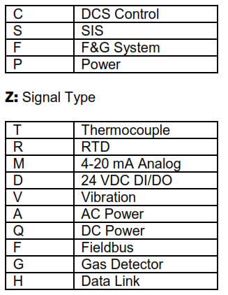
8.2.1. Cables and junction boxes shall be segregated by system and signal type. Refer to AppendixB for details.
8.2.2. The signals for systems identified in Appendix-B, under “Y” as well as signal types and under “Z” shall not be combined in the same junction box.
8.2.3. SIS circuits shall be segregated from non-SIS circuits and shall have dedicated junction boxes.
8.2.4. Intrinsically safe systems and fire and gas detection systems shall be segregated from other wiring and shall have dedicated junction boxes.
8.2.5. For segregation of fire and gas detection system cabling and wiring refer to SES-F01-G01.
8.2.6. The minimum separation between signal and power cables shall be per PIP PCCEL001.
8.3. Control Network Cables
8.3.1. Refer to SES-X05-S01 for the specification of fiber optic, UTP and coaxial cables.
8.3.2. Types of cable and installation of control network shall be in accordance with the recommendation of the manufacturers.
8.3.3. In general, fiber optic cables shall have minimum 12 fibers with 100 percent spare fibers. All fiber optic cables shall be terminated and labeled in patch panels.
8.3.4. Fiber optic cables shall be tested for integrity and cable length using an optical time domain reflectometer (OTDR). Cables shall be tested on the reel before installation, and when installed and terminated. All fibers, including spares, shall be tested.
8.3.5. An end-to-end attenuation test to calculate optical power loss shall be performed after the installation is complete. This test shall encompass all elements such as fiber, connectors, and jumpers that will make up the complete fiber optic link.
8.3.6. Fiber optic cable routing, cable support, and protection systems shall be chosen and engineered to preclude the need to splice cables.
8.4. Fireproofing and Fire Protection
8.4.1. Refer to SES-F02-E01 for fireproofing requirements.
8.4.2. Refer to SES-X05-S01 for fire resistant type cable specifications.
8.4.3. Wire and cable in buildings shall comply with the fire codes and fire suppression protection required for buildings containing electrical equipment.
8.4.4. Control network cables shall be protected from fire by routing only in fire-safe areas. Redundant paths of communication cables shall be chosen to preclude simultaneous fire potential to both paths.
8.5. Building Entries and Inside Buildings
8.5.1. Cables can enter the building either underground or above ground directly through the wall, regardless of the cable installation method.
8.5.2. Underground entry shall be through removable metal plates with cable glands that shall terminate the steel wire armor. Cable glands shall meet the area classification requirement of the cable on JB side. Refer to SES-X06-C01 for details. Alternative method for building entry shall require approval.
8.5.3. Above ground cable entry wall penetration to the building shall be as follows:
a. Weatherproof seal shall be provided,
b. Fireproof seal shall be provided, if specified,
c. Drip shields shall be provided on the tray,
8.5.4. As a minimum, conduit and homerun cable entries into pressurized unclassified locations shall have conduit seals or transit windows to reduce loss of enclosure pressurization.
8.5.5. Signal and control network cables internal to the building shall be beneath elevated floors in cable trays.
8.5.6. Cables routed in cable trays beneath the elevated floor will not be required to be armored.
8.5.7. Cables shall be secured with a clamping rail within 50 cm of the cable entry to the cabinet.
8.5.8. Refer to SES-E11-E02 for grounding and lightning protection.
8.5.9. All exposed openings in the elevated floor shall be sealed so that the fire suppression system will be contained under the elevated floor.
9. Wiring
9.1. General
9.1.1. Refer to SES-R11-C02 for instrument electrical connections.
9.1.2. All wiring shall be in accordance with NFPA 70.
9.1.3. Wire colors for instrument wiring shall be consistent throughout the project and shall be as per SES-X05-S01.
9.1.4. Refer to Appendix-A for the wire and cable minimum requirements for instrument circuits.
9.1.5. 230 VAC wiring to solenoid valves, relays, and other electro-mechanical devices shall be sized to have a voltage drop of less than 5 percent.
9.1.6. DC wiring to solenoid valves, relays, and other electro-mechanical devices shall be sized to have a voltage drop of less than 10 percent.
9.1.7. All pairs in homerun multi pair cables shall be terminated at the junction box end and at the marshalling panel end.
9.1.8. Wiring within enclosures shall be run in the PVC closed, slotted ducts. Wires inside each duct shall be strapped neatly in bundles and run to the termination points. Ties shall be the nylon, lock type.
9.1.9. Wiring shall be adequately spaced such that any single wire can be removed from its terminal without disturbing other wire terminations and without using special tools.
9.1.10. Wire lugs shall be used for stranded wires. For special connections without lug, approval shall be obtained.
9.1.11. Thermocouples shall use floating circuits. Extension cable shields shall be grounded at one point only at cabinets’ location.
9.1.12. The material of the extension cable conductors shall be the same as that of the associated thermocouple.
9.1.13. All analog signal wiring shall be shielded, except where noted.
9.1.14. All analog signal wiring shields shall be floated at the instrument, carried through the junction box and tied to the instrument ground bus at the marshalling cabinet.
9.2. Terminal Requirements
9.2.1. Screw type or spring type terminals can be used per application requirements.
9.2.2. The size of terminals specified below are the guidelines, however required sizes of the terminals shall be decided during project engineering.
9.2.3. Side entry terminals shall be used.
9.2.4. Selection of terminal vendor shall be approved by SABIC.
9.2.5. Feed through type terminals of 2.5 mm2 shall be used for following:
a. All signal terminations in junction boxes
b. All shield terminations in junction boxes
c. All thermocouple and RTD terminations in junction boxes, marshalling cabinets, control system cabinets and local panels.
Note: The requirements of compensating type terminals for thermocouple terminations shall be evaluated per project.
9.2.6. Swing link disconnect with knife edge type terminals of 2.5 mm2 shall be used in the marshalling cabinets, control system cabinets and local panels for analog input, (except thermocouple and RTD), and analog output signals, to isolate field signals during maintenance.
9.2.7. Swing link disconnect with fuse type terminals of 2.5 mm2 with fuse, and burned-out LED indicator shall be used in the marshalling cabinets, control system cabinets and local panels for digital input and digital output signals only on the positive (+) side of a loop.
9.2.8. Yellow and green color ground terminals of 2.5 mm2 shall be used for shield termination.
9.2.9. All terminals shall be mounted on DIN rail. DIN rails shall be electrically isolated and shall have provisions for connecting to the instrument ground.
9.2.10. For intrinsically safe application, the terminals and cable ducts shall be blue color. IS cables, wires and ducts shall be segregated from non-IS ones.
9.3. Terminations
9.3.1. Wire pairs and shield shall be terminated on adjacent terminals.
9.3.2. Cable shields or drain wires shall not be used as conductors.
9.3.3. Communication and overall drain wire shall be terminated.
9.3.4. Special stripping tool shall be used to avoid installing cable insulation under terminal pressure plate.
9.3.5. Wiring shall be terminated on terminals only. Soldering and wire nut splicing shall not be used.
9.3.6. One terminal shall be used for one wire only.
9.3.7. When multiple connections are required, terminal manufacturer’s jumper bars shall be used.
9.3.8. Wire terminations shall be done as described below:
a. All wiring shall be neatly dressed out and bundled with nylon ties.
b. All wire labels shall be installed such that they are visible.
c. Ratcheting type compression tools made by the same manufacturer as the lug shall be
used.
d. Solid conductor wire terminations to screw terminals shall be made by forming an eye of the same size as the screw in a 270 degree arc around the screw.
e. All terminations shall be torqued to insure proper connection.
9.3.9. Twisted pairs and triads shall be left twisted to within 50 mm of the termination point.
9.4. Wire Tagging
9.4.1. All termination of wires shall be labeled by installing “heat shrink” labels.
9.4.2. The label shall be applied so that the identification is visible without detaching or relocating wires or cable.
9.4.3. Wire tag information shall be permanently marked in alpha numeric on tubular, heat shrinkable, slip-on sleeves. Wrap-around, snap-on or self-adhesive wire markers shall not be used. Handwritten wire tags are not acceptable.
9.4.4. All wiring shall be tagged at each end. Each wire shall have label specifying the source and destination information to be imprinted on one heat shrink sleeve.
9.4.5. Spare wires shall be tagged spare unless noted otherwise.
9.4.6. Where wires terminate on instrument or device terminals, the instrument tag number and terminal designation (+) or (-) shall be used in lieu of terminal strip identification, e.g. 71-TE1101(+).
9.4.7. Spare wires shall be terminated and grounded at the specified point in the equipment room, and marked as “Spare”.
9.4.8. These requirements apply only to the wire labels and are not required on the documentation.
9.4.9. Following are examples of tagging for a typical 4-20 mA analog signal loop.
At transmitter end (71-FT-1101)
71-FT-1101(+)
71-FT-1101(-)
At junction box (71-CMJB-010) for single pair cable from transmitter
71-FT-1101(+)/7
71-FT-1101(-)/8
At junction box (71-CMJB-010) for homerun cable connected to marshalling cabinet (70RIB2-DCS-MC-001)
7/ 70RIB2-DCS-MC-001-TS1-21
8/ 70RIB2-DCS-MC-001-TS1-22
Note: Shield connected to JB terminal is not required to be provided with the tag.
At marshalling cabinet (70RIB2-DCS-MC-001) for homerun cable coming from JB (71-CMJB-010)
71-CMJB-010-7/71-FT-1101-TS1-21
71-CMJB-010-8/71-FT-1101-TS1-22
Note: Shield connected to marshalling cabinet terminal is not required to be provided with the tag
10. Auxiliary and Non-System Cabinets Internal Wiring
10.1. General
10.1.1. Refer to SES-X01-E01 for cabinets requirements in control systems.
10.1.2. Refer to SES-X05-S02 for instrument control panels’ requirements.
10.1.3. Refer to SES-X05-S01 for cables specification and Appendix-A for wire and cable minimum requirements for instrument circuits.
10.1.4. Refer to SES-R11-C02 for wiring into junction box.
10.1.5. For the terminal requirements in auxiliary and non-system cabinets refer to wiring clause of this document.
10.1.6. For interposing relay cabinet numbering refer to SES-D03-D05.
11. Numbering, Tagging and Naming Format
11.1.1. The typical formats given in the appendixes shall be applied to grass-root projects.
11.1.2. In other projects the existing practice shall be followed.
11.1.3. The numbering, tagging, and naming format of cable, wire, and cabinet shall be approved.
11.1.4. Refer to Appendix-C and Appendix-D for system cabinet, and local panel numbering formats.
12. Wire and Cable Minimum Requirements for Instrument Circuits
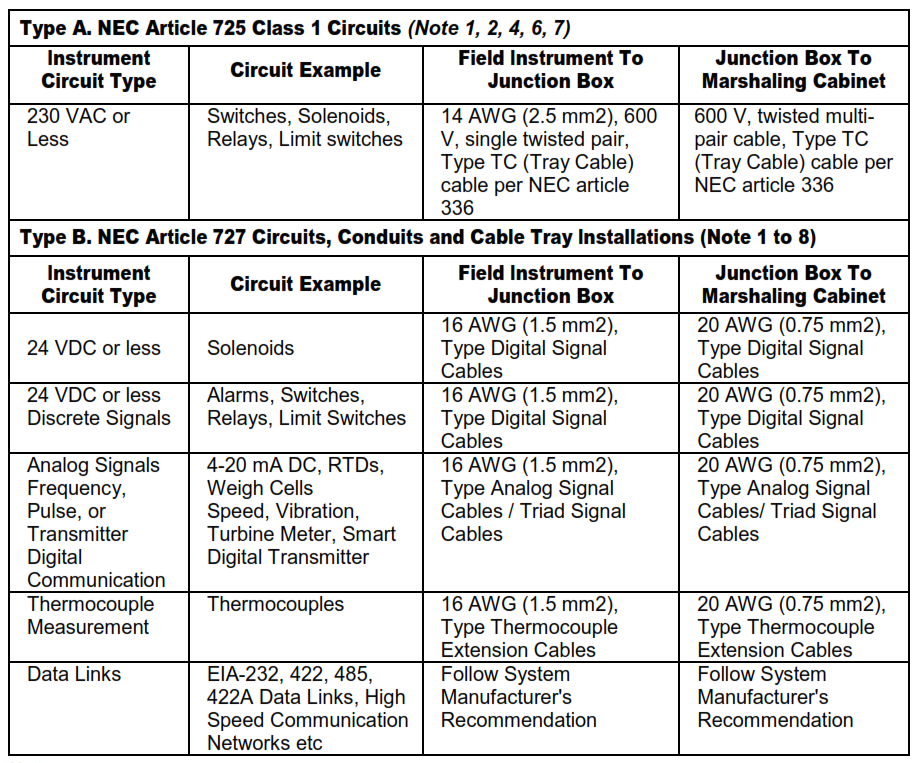
Notes:
1. Cables installed in classified area shall meet the NFPA 70 requirements.
2. The minimum size for multi-pair/triad cable shall be 20 AWG (0.75 mm2). The minimum wire size for single pair cable shall be 16 AWG (1.5 mm2). A larger wire size shall be used if required by the calculations.
3. Type ITC cable per SES-X05-S01 shall not be installed on either non-power limited circuits or powered limited circuits operating at more than 150 volts or more than 5 amperes.
4. Differences in the manufacturer recommended cable and these requirements shall be approved by Company.
5. Refer to SES-X05-S01 for the specification of the types of cables.
6. Type A circuits shall be separated from all other types of instrument circuits by either conduit tray dividers or separate trays.
7. Wire sizes listed in this table and notes are minimum requirements. Actual wire size shall be based on load current and voltage drop requirements. The use of parallel wires to meet the current requirements shall not be permitted.
8. Physical barriers shall be provided to separate intrinsically safe wiring from other wiring.
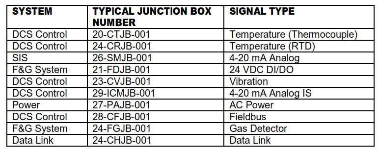
13. Junction Box Numbering
13.1. Typical Format
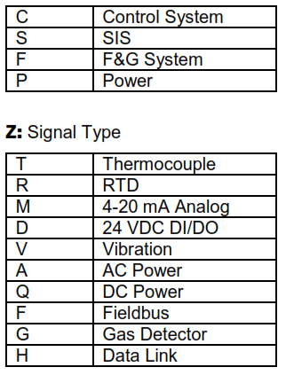
AA-YZJB-XXX
Where, AA: Process Unit no from 00 to 99 and Y: System
JB: Abbreviation for Junction Box
XXX: Sequence number starting from 001 to 999
Note: 1. “I” should be added when intrinsically safe junction box is required, e.g. 12-ICTJB-001
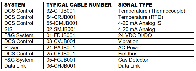
13.2. Examples of Junction Box Numbering
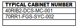
14. Cabinet Numbering
14.1. Typical Format
AACCCn-DDDD-BBBBB-XXX
Where, AA: Process plant number from 00 to 99
CCC: Building symbol, example: RIB, CR, RR
n: Building sequence number, from 0 to 9
DDDD: System type
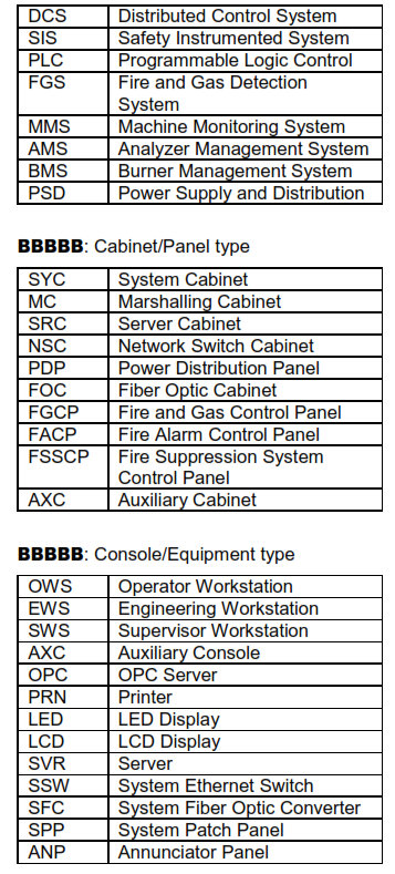
XXX: Cabinet sequence number starting from 001 to 999
Note: 1. Non listed system, console, and equipment types definitions shall be defined per project requirement and approved by SABIC.
14.2. Examples of Cabinet Numbering
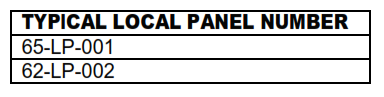
15. Local Panel Numbering
15.1. Typical format
AA-LP-XXX
Where,
AA: Process unit number from 00 to 99
LP: Local Panel
XXX: Local panel sequence number starting from 001 to 999
15.2. Examples of LP Numbering
16. Homerun Cable Numbering
16.1. Typical format
AA-YZBB-XXXK
Where,
AA: Process unit number from 00 to 99
Y: System
BB: Panel type, example JB= Junction Box, LP=Local Panel.
XXX: Panel sequence number starting from 001 to 999.
K: Cable sequence number applies, when more than one homerun cables are connected to the same panel, e.g. 12-CTJB-001A, 12-CTJB-001B. “A” stands for 1st cable, same way “B” shall be for 2nd cable and so on.
Note: 1. “I” should be added, when intrinsically safe cable is required, e.g. 22-ICTJB-001A, 23-ICRLP-001A
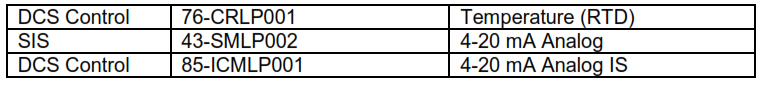
16.2. Examples of homerun cable numbering