The blog content provides an in-depth explanation of Overcurrent Relay (OCR) functioning, types, and the protection it offers within electrical power systems.
An Overcurrent Relay (OCR) is a type of protective device that activates or picks up when the current flowing through a circuit exceeds a predetermined threshold, known as the setting value. It is used to safeguard electrical power systems from excessive currents caused by short circuits, ground faults, and other faults. OCRs can be applied to protect various elements of a power system, including transmission lines, transformers, generators, and motors.
In feeder protection, multiple OCRs are typically employed to safeguard different sections of the feeder. These OCRs must coordinate with each other to ensure that the relay closest to the fault operates first. Coordination is achieved by setting appropriate time-current characteristics for each OCR, or by using a combination of time-delay and current-sensing features. This coordination ensures that the OCR nearest to the fault clears the fault without unnecessary tripping of other OCRs further upstream.
Overcurrent Relay gives protection against:
Over Current Relay provides protection against various types of faults, including:
- Short circuits: Overcurrent relays offer protection against short circuits, which occur when there is an unintended connection between two conductors with different potentials, resulting in excessive current flow.
- Phase faults: These faults involve a short circuit or other abnormal condition occurring between two phases of a three-phase electrical system.
- Ground faults: Ground faults occur when a conductor makes unintended contact with the ground or an unintended conductive surface, resulting in current flow to ground.
- Winding faults: Winding faults involve a short circuit or other abnormal condition occurring within the windings of a transformer or motor.
Short-circuit currents typically reach values several times higher than the full load current. Therefore, rapid clearance of faults is essential to prevent damage to equipment and ensure the safety of the electrical system.
Primary Requirements Overcurrent Protection:
The primary requirements of Over Current Protection are:
- The protection should not operate for starting currents, permissible overcurrents, or current surges. To achieve this, time delay is provided, especially in the case of inverse relays, to ensure that the protection responds only to actual faults and not to transient conditions.
- The protection should be coordinated with neighboring overcurrent protection devices. Coordination ensures that the relay nearest to the fault operates first, minimizing the extent of the outage and allowing for targeted fault isolation.
- Overcurrent relay serves as a fundamental component of overcurrent protection systems. It detects abnormal current conditions and initiates protective actions to prevent damage to equipment and ensure the integrity of the electrical system.
Purpose of Overcurrent Protection:
The purposes of overcurrent protection are:
- Detect Abnormal Conditions: Overcurrent protection systems are designed to detect abnormal current levels in electrical circuits, which may indicate faults such as short circuits, ground faults, or overloads.
- Isolate Faulty Parts of the System: Upon detection of abnormal currents, overcurrent protection devices work to isolate the faulty section of the electrical system by interrupting the flow of current to prevent further damage.
- Ensure Fast Operation to Minimize Damage and Danger: Overcurrent protection devices are engineered to operate swiftly in response to faults, minimizing the duration of abnormal conditions and reducing the risk of damage to equipment and danger to personnel.
- Discriminate and Isolate Only the Faulty Section: Overcurrent protection systems aim to discriminate between genuine faults and transient conditions, ensuring that only the faulty section of the system is isolated while allowing unaffected sections to remain operational.
- Dependability and Reliability: Overcurrent protection devices must be dependable and reliable, consistently performing their intended functions under various operating conditions to ensure the safety and integrity of the electrical system.
- Security and Stability: Overcurrent protection enhances the security and stability of the electrical system by preventing excessive currents that could lead to equipment damage, power outages, or safety hazards.
- Cost of Protection and Mitigation of Potential Hazards: Overcurrent protection systems provide cost-effective solutions for mitigating potential hazards associated with abnormal current conditions, helping to minimize downtime, repair costs, and safety risks.
Over Current Relay Ratings
Overcurrent relay ratings are crucial for their proper operation and ensuring the safety of electrical systems. These ratings typically include voltage, ampere, and interrupting ratings.
- Voltage Rating: The voltage rating of the overcurrent protective device should be equal to or greater than the circuit voltage it is intended to protect. While it’s acceptable for the device’s rating to exceed the system voltage, it should never be lower.
- Ampere Rating: The ampere rating of an overcurrent protective device should generally not exceed the current-carrying capacity of the conductors it is connected to. As a rule of thumb, the ampere rating of the device is selected at around 80% of the continuous load current.
In addition to these ratings, current limiting can also be considered as another characteristic of overcurrent protective devices, although it’s not mandatory for all devices to have this feature. Proper selection of these ratings is essential to prevent hazards to both equipment and personnel, as inadequate ratings can lead to serious risks in case of faults.
Difference between Overcurrent protection and Overload protection:
Here’s the difference between overcurrent protection and overload protection presented in a table format:
| Aspect | Overcurrent Protection | Overload Protection |
|---|---|---|
| Purpose | Protects against excessive currents or short circuits | Prevents damage due to overheating from prolonged excessive current |
| Functionality | Safeguards against currents beyond acceptable ratings | Addresses situations where current causes overheating |
| Scope | Covers various scenarios like short circuits, ground faults, and overloads | Specifically focused on preventing damage from prolonged excessive current |
| Subset Relation | Overload protection can be considered a subset | Overcurrent protection can encompass overload protection, but dedicated devices are often used for motor loads |
| Application in Motors | Overcurrent relays may serve as overload protection for resistive loads | Dedicated overload relays with longer time settings are typically used |
Overcurrent Relay Types:
- Instantaneous Overcurrent (Define Current) Relay
- Define Time Overcurrent Relay
- Inverse Time Overcurrent Relay (IDMT Relay)
- Moderately Inverse Relay
- Very Inverse Time Relay
- Extremely Inverse Relay
- Directional Overcurrent Relay
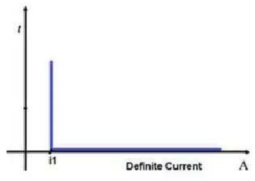
1. Instantaneous Overcurrent (Define Current) Relay
The Instantaneous Overcurrent Relay, also known as the Definite Current Relay, operates with a swift response when the current surpasses a predetermined threshold. Its operation is characterized by a fixed time frame, triggered solely by the magnitude of the current without any intentional delay. This relay type is distinguished by its constant operating time, typically within 1.5 seconds or less, ensuring rapid reaction to overcurrent conditions.
In terms of coordination, Definite Current Relays are strategically placed along the circuit based on the variation of fault currents relative to the source impedance. Relays positioned farther from the source are configured to trigger at lower current values, while those closer to the source have progressively higher operating currents. This coordinated approach optimizes the protection scheme, effectively mitigating overcurrent events across the network.
Applied predominantly to outgoing feeders, the Definite Current Relay serves as a vital component in safeguarding electrical systems against excessive currents. Its instantaneous response capability enhances system reliability by swiftly isolating faulted sections, thereby minimizing potential damage and ensuring operational continuity. It operates in 0.1or less.
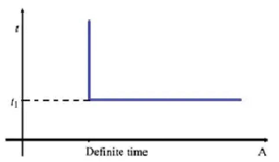
2. Definite Time Overcurrent Relay
Definite Time Overcurrent Relays are designed to trip when two conditions are met: the current exceeds the set value, and the fault persists for a duration equal to the relay’s time setting. These relays may feature multiple protection stages, each with its own current and time settings, facilitating a customizable protection scheme.
Operationally, Definite Time Overcurrent Relays maintain a constant tripping time, regardless of the current magnitude above the pickup value. They incorporate pickup and time dial settings, enabling users to configure the desired time delay using intentional mechanisms.
While relatively easy to coordinate and offering constant tripping time, these relays have drawbacks. They may struggle to maintain supply continuity at the load end during faults, and their time lag, albeit intentional, may not be ideal for short circuits. Additionally, they require adjustments with load additions and may not be suitable for long-distance transmission lines where rapid fault clearance is critical.
Definite Time Overcurrent Relays find application as backup protection for distance and differential relays, with adjustable time delay settings. They are also deployed as primary protection for outgoing feeders and bus couplers, providing reliable protection with customizable time delay settings.
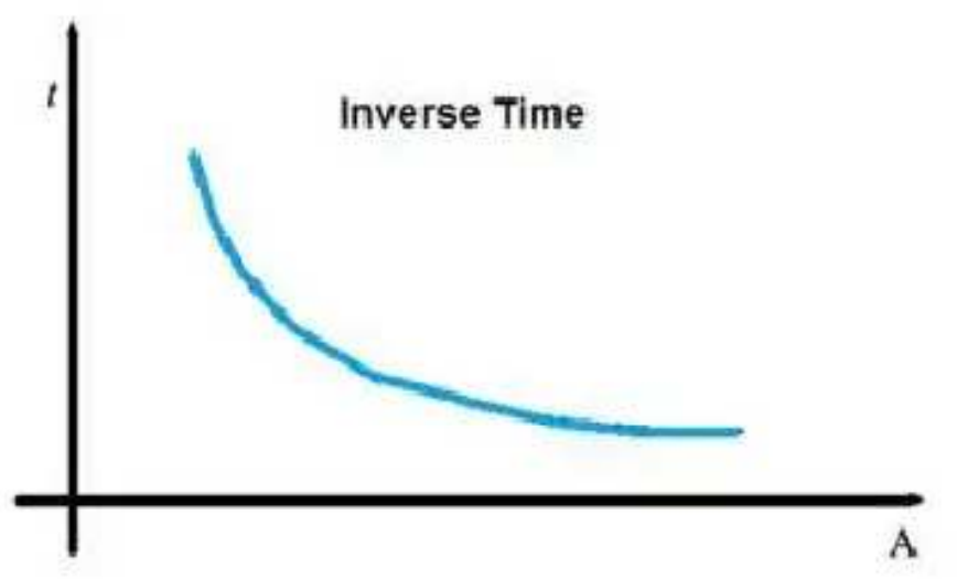
3. Inverse Time Overcurrent Relay (IDMT Relay)
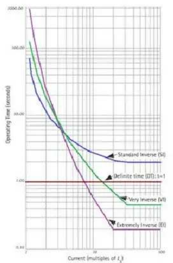
Inverse Time Overcurrent Relays (ITOC), also known as Inverse Definite Minimum Time (IDMT) relays, exhibit operating times that vary inversely with the fault current. This means that higher fault currents will cause the relay to operate faster compared to lower fault currents. There are three main types of inverse time characteristics: standard inverse, very inverse, and extremely inverse.
Discrimination in inverse time relays is achieved by considering both time and current. The operating time of the relay is inversely proportional to the fault current, allowing for effective discrimination between different fault conditions.
These relays are commonly referred to as Inverse Definite Minimum Time (IDMT) relays due to their inverse time-current characteristics.
The operating time of an overcurrent relay can be adjusted by changing the time dial setting. The lowest time dial setting typically corresponds to the fastest operating time, around 0.5, while the slowest setting is around 10.
Inverse Time Overcurrent Relays operate when the current exceeds their pickup value, and their operating time varies depending on the magnitude of the current.
These relays exhibit inverse time-current characteristics at lower fault current values, providing quick response to faults, and definite time characteristics at higher fault current values, ensuring stability and reliability.
The type of inverse characteristic obtained depends on the value of the plug setting multiplier. Values below 10 result in inverse characteristics, while values between 10 and 20 tend towards definite time characteristics.
Inverse Time Overcurrent Relays are widely used for the protection of distribution lines due to their ability to provide effective protection against various fault conditions.
Based on their inverse characteristics, these relays are classified into three main types, each suitable for different applications and fault conditions.
Based on the inverseness it has three different types.
Here’s a breakdown of the different types of overcurrent relays:
1. Normal Inverse Time Overcurrent Relay:
- Provides a moderate level of inverse characteristics.
- Typically accurate within 5 to 7.5% of the nominal operating time.
- Used in circuits where fault current depends on system generating capacity.
- Grading margin may range from 0.4 to 0.5 seconds.
- Commonly applied in utility and industrial circuits.
2. Very Inverse Time Overcurrent Relay:
- Offers stronger inverse characteristics compared to IDMT relays.
- Suitable for situations where fault current decreases with distance from the source, such as ground faults.
- Effective in protecting against faults with substantial reductions in fault current as distance increases.
- Grading margin can be reduced to 0.3 to 0.4 seconds.
- Used when fault current is dependent on fault location and independent of normal changes in generating capacity.
3. Extremely Inverse Time Overcurrent Relay:
- Provides even stronger inverse characteristics than very inverse relays.
- Ideal for protecting machines against overheating.
- Operating time is approximately inversely proportional to the square of the current.
- Allows for short time delay despite high switching-in currents.
- Used when fault current is dependent on fault location and independent of normal changes in generating capacity.
- Suitable for protecting distribution feeders with peak currents on switching in and for coordinating with fuses and reclosers.
4. Long Time Inverse Overcurrent Relay:
- Primarily used as backup earth fault protection.
- Offers longer time delays compared to other types of overcurrent relays.
- Commonly employed for protecting against prolonged overcurrent conditions.
Each type of overcurrent relay has its specific characteristics and applications, allowing for tailored protection in various electrical systems.
Connection of Overcurrent and Earth Fault Relay:
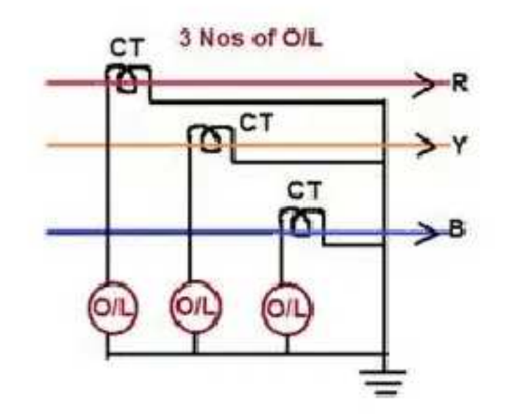
3 Nos O/C Relay for Overcurrent and Earth Fault Protection:
- Operation:
- All 3-phase overcurrent relays act during 3-phase faults.
- Only relays in affected phases operate during phase-to-phase faults.
- Relay in the faulty phase operates for single line to ground faults.
- Sensitivity Concerns: Sensitivity desired for earth leakage protection cannot be achieved with overcurrent relays due to higher current settings.
- Neutral Connection: Star points of both CT secondary’s and relay windings should be connected by a neutral conductor to ensure reliable operation during single phase to earth faults.
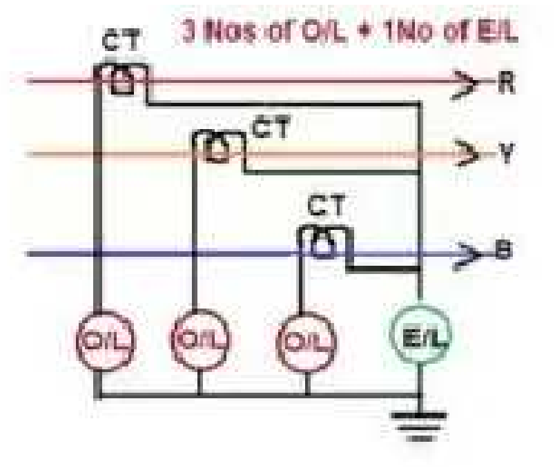
3 No O/C Relay + 1 No E/F Relay for Overcurrent and Earth Fault Protection:
- Normal Conditions: Under normal and three-phase fault conditions, currents cancel out, and no current flows through the earth fault relay.
- Phase-to-Phase Faults: Only overcurrent relays in affected phases operate during phase-to-phase faults.
- Earth Faults: Earth fault relay operates only during earth faults. Caution needed to avoid short-circuiting the relay by grounding both CT secondary star point and relay winding star point.
2 No O/C Relay + 1 No E/F Relay for Overcurrent and Earth Fault Protection:
- Fault Detection:
- Two overcurrent relays respond to phase faults, and at least one operates for faults involving two phases.
- Earth fault relay is relied upon for ground faults.
- Economical Version: Saves one overcurrent relay compared to the 3-O/C and 1-E/F protection scheme.
- Complete Protection: Provides comprehensive protection against both phase and ground faults.
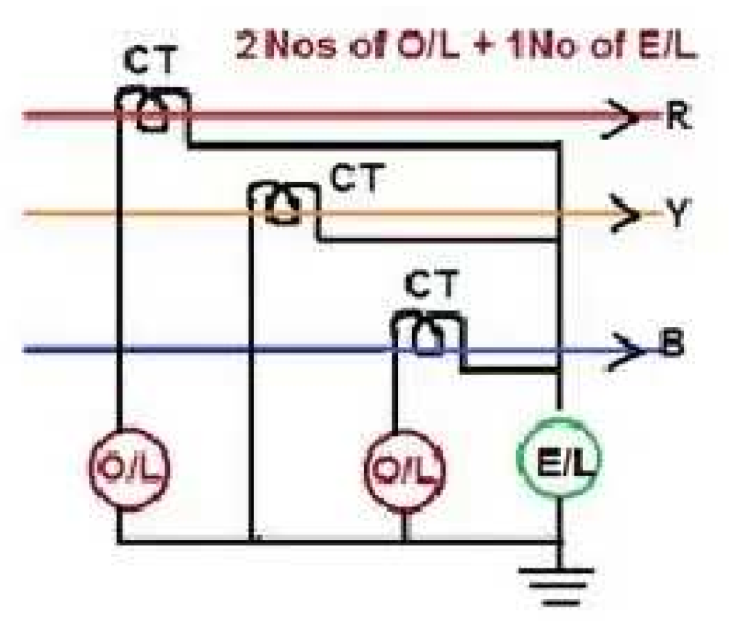
These configurations ensure effective protection against various fault conditions while considering sensitivity, reliability, and cost-effectiveness. Proper connection and coordination are crucial for reliable operation and fault detection.
Current Transformer Secondary Connections:
To ensure correct directional sensitivity of the protection scheme, the star point on the secondary side of Current Transformers (CTs) should be made as follows for the protection of various equipment of Extra High Voltage class:
- Transmission Lines: Connect the star point on the line side of the CTs.
- Transformers: Connect the star point on the transformer side of the CTs.
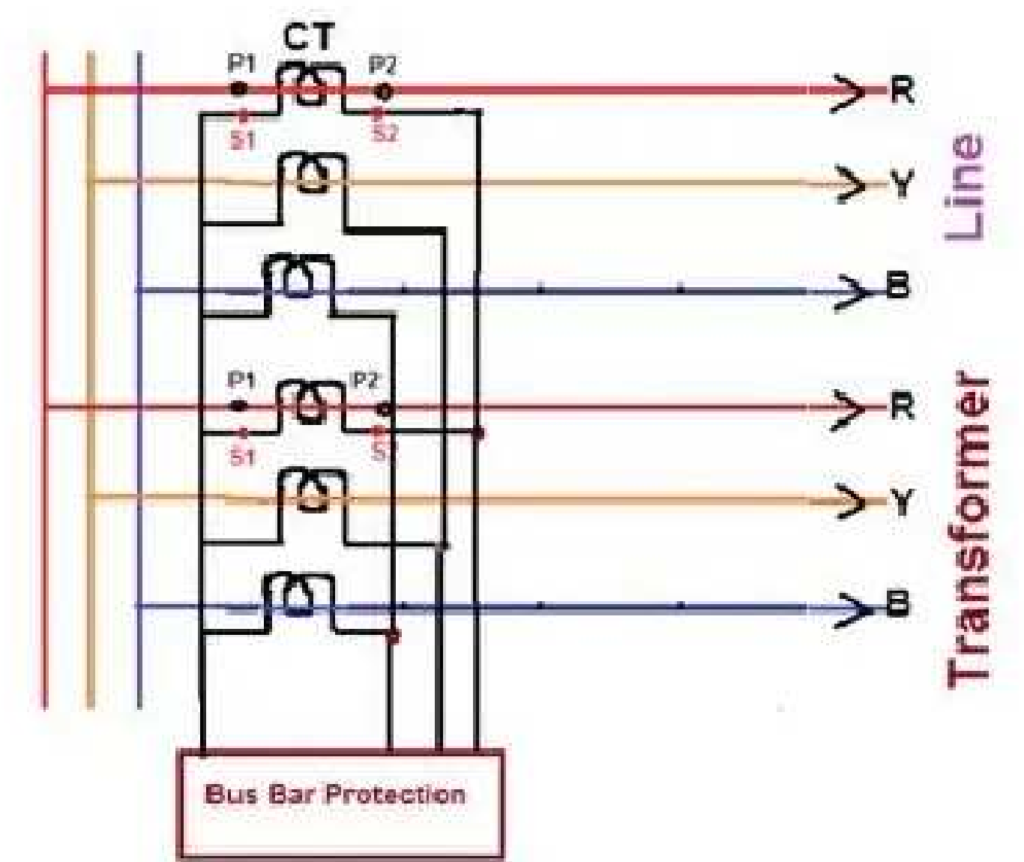
For Bus bar – Bus side
Generator Protection:
Generator Protection – Generator Side
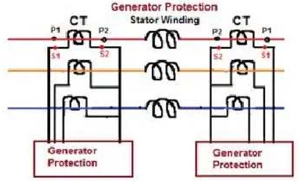
The method outlined above must be followed regardless of the polarity of Current Transformers (CTs) on the primary side. Specifically, for line protection scenarios:
- If ‘P1’ (Primary Side 1) is oriented towards the bus, then ‘S2’s (Secondary Side 2) of the CTs should be shorted.
- If ‘P2’ (Primary Side 2) is oriented towards the bus, then ‘S1’s (Secondary Side 1) of the CTs should be shorted.
Standard Overcurrent and Earth Fault Protection
| No. | Name of the Equipment | |
| 1 | 11 KV Feeders. | (A) 2 No Over Current and one no Earth Fault IDMT relays (B) 2 No Instantaneous Over current (highest) and one no Instantaneous Earth fault relay |
| 2 | 8 MVA Capacity OR Two Transformer in a Substation (Irrespective of Capacity). | HV side: 33 KV Breaker (Individual or Group Control with 3 Over Current and One Earth Fault IDMT relays. LV Side: Individual 11 KV Breakers with 3 Over Current and One Earth Fault IDMT relays |
| 3 | 8 MVA Power Transformer. | Differential relays OR REF relays on LV side |
| 4 | Only one PTR in a Substation (Less than 8 MVA). | HV Side: HG fuse. LV Side: 11 KV Breaker with 3 Over Current and one E/F IDMT relay. |
Types of Protection:
Protection schemes in electrical systems can be categorized into two major groups: Unit schemes and Non-unit schemes.
- Unit Type Protection:
- Unit type schemes protect specific areas of the system such as transformers, transmission lines, generators, or bus bars.
- These schemes are based on Kirchhoff’s current law, stating that the sum of currents entering an area must be zero. Any deviation indicates an abnormal current path.
- Unit protection schemes ignore disturbances or operating conditions outside the protected area and are designed to be stable above the maximum possible fault current.
- Non-unit Type Protection:
- Non-unit schemes also protect specific areas but without fixed boundaries, allowing protection zones to overlap into other areas.
- While providing backup purposes, overlapping protection zones may isolate larger areas if faults are detected by different non-unit schemes.
- Non-unit protection systems incorporate various schemes, including time-graded overcurrent protection, current-graded overcurrent protection, and distance or impedance protection.
Non-unit Protection Schemes:
(A) Time-Graded Overcurrent Protection:
- Simplest method to protect a line, relying on the fact that fault current increases significantly above maximum load current during a fault.
- Limited to simple and non-costly equipment due to its simplicity.
(B) Earth Fault Protection:
- Involves employing two or three overcurrent relays and a separate relay for single-line-to-ground faults.
- Earth fault relays are faster and more sensitive as earth fault currents are typically smaller than phase fault currents.
- Relays used for earth fault protection differ from those used for phase-to-phase fault protection due to differences in fault current magnitude.
Various Types of Line Faults:
| No. | Type of Fault | Operation of Relay |
| 1 | Phase to Ground fault (Earth Fault). | Earth Fault Relay. |
| 2 | Phase to Phase fault Not with Ground. | Related Phase Over current relays. |
| 3 | Double phase to Ground fault. | Related Phase Over current relays and Earth Fault relays. |
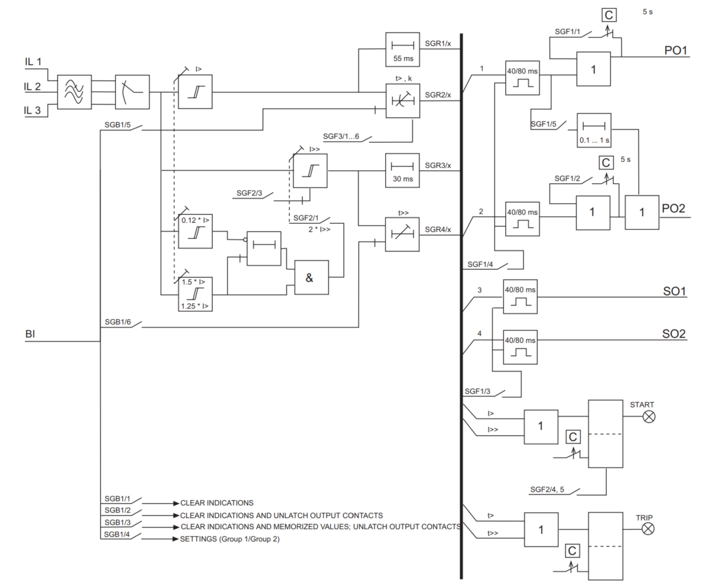
Overcurrent Relay Block diagram