Power Transformer play a crucial role in our modern power systems, enabling the efficient transfer of large amounts of electrical power over significant distances. The challenge arises because large generators typically operate at a practical design voltage of about 25 kV, while transmitting hundreds of megawatts requires much higher line voltages ranging from 161 to 1000 kV. The solution to this voltage disparity lies in the transformative capabilities of transformers.
Transformers have the ability to step up or step down voltages with minimal power loss. By introducing a step-up transformer between the generator and a transmission line, it becomes possible to maintain a practical voltage for the generator while achieving an effective transmission line voltage. Subsequently, employing step-down transformers along the transmission line, connected to various electrical loads, allows the utilization of transmitted power at a safe and manageable voltage level. This transformative capability is fundamental to the development and functionality of large-scale power systems.
In an ideal scenario, a transformer is expected to maintain the power factor and have zero internal power loss. If P1 represents the input power for a three-phase transformer and P2 denotes its output power, the relationship for an ideal three-phase transformer is defined by the following equation:
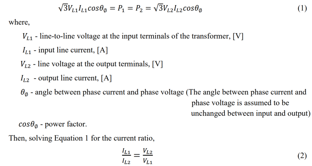
Certainly, when a transformer steps up the voltage, it simultaneously reduces the current in a proportional manner. This relationship is crucial for enhancing the efficiency of power systems. The reason lies in the fact that the losses incurred in transmission lines are directly proportional to the square of the line current I2R. Consequently, the ability of transformers to elevate transmission line voltages significantly contributes to the overall efficiency improvement by diminishing the line currents.
Introduction to Power Transformer
A transformer is a device with four terminals that transforms an AC input voltage into a higher or lower AC output voltage. It facilitates the transfer of power between different circuits without changing the frequency, regardless of the voltage levels. The key components of a transformer include the primary winding (input), the secondary winding (output), and the iron core, which enhances the generated magnetic field. Unlike many devices, transformers have no internal moving parts and operate based on electromagnetic induction.
The primary purpose of transformers is to change voltages, and they are particularly valuable in power systems where voltage adjustments are required. Power transformers, specifically those rated 500 kVA and larger. The structure of a typical power transformer is shown in Figure 1.
![What is Power Transformer? Explanation for Engineers [PDF]](https://paktechpoint.com/wp-content/uploads/2024/02/image-2-1024x705.png)
Transformers enable the transfer of electrical energy between circuits while keeping them completely insulated from each other. This insulation allows the use of very high voltages for transmission lines (stepped-up), resulting in lower currents (stepped-down). The advantage of higher voltage and lower current is a reduction in the size and cost of transmission lines, along with minimized transmission losses.
One notable feature of transformers is their reliability, which often leads to neglect in terms of maintenance. However, regular care and maintenance are crucial for ensuring their continued performance and preventing premature failure. Despite their reliability, overlooking maintenance can reduce service life and, in some cases, lead to outright failure. Therefore, proper attention to maintenance is essential for maintaining the efficiency and longevity of transformers.
Principle of operation
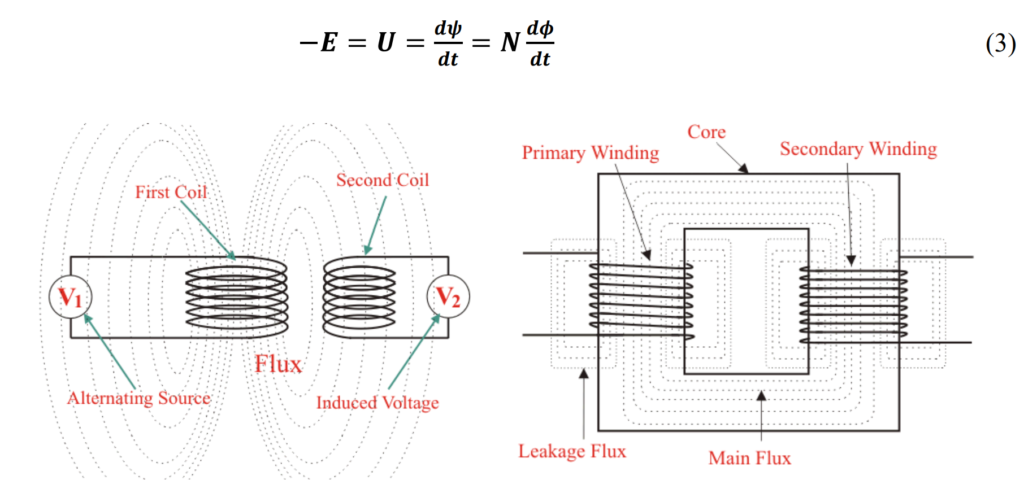
The operation of a transformer is based on the principle of efficient transfer of electrical energy through magnetic induction between two circuits. When one winding of the transformer is supplied with AC power, it generates an alternating magnetic field within the transformer core. This field, known as “flux,” circulates through the core. With a second winding wrapped around the same core, voltage is induced by the alternating flux lines. Connecting a circuit to the terminals of the second winding allows for the flow of current.
In a power transformer, each phase consists of two separate coil windings wound on a shared core. The low-voltage winding is positioned closer to the core, while the high-voltage winding is placed around both the low-voltage winding and the core. Figure 2 illustrates the internal construction of one phase. The core is typically made from thin steel laminations, each coated with insulation to reduce losses. This steel core provides a low-resistance path for the magnetic flux. Both high-voltage and low-voltage windings are insulated from the core and each other, with leads brought out through insulating bushings.
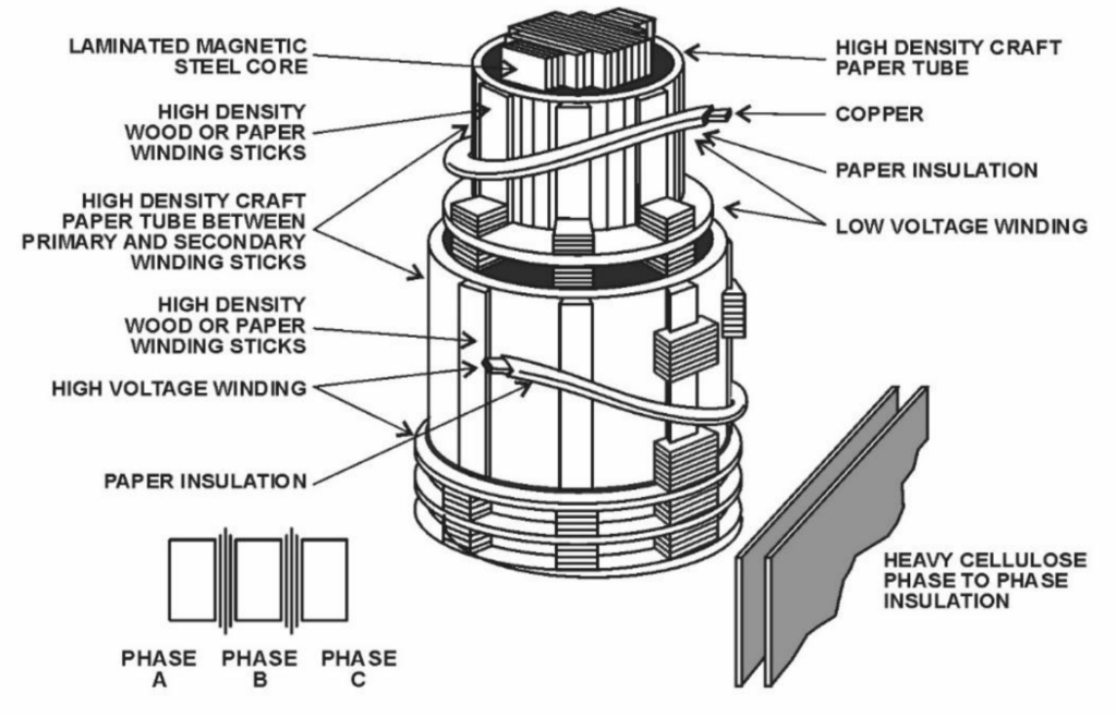
In the case of a three-phase transformer, the core has three legs, and around each leg, there are both high-voltage and low-voltage windings. Special paper and wood are utilized for insulation and internal structural support in the transformer, ensuring proper isolation and stability.
Power Transformer Working Principle
In essence, a transformer is a straightforward, stationary electromagnetic passive electrical device that operates based on Faraday’s law of electromagnetic induction to convert electrical energy from one value to another. The transformation in an electrical transformer is achieved through mutual induction between two or more windings. According to Faraday’s Laws of Electromagnetic Induction (specifically the second law), the electromotive force (emf) induced in a coil is equal to the rate of change of flux linked with the coil. The flux linkage is the product of the number of turns in the coil and the flux associated with the coil.
As mentioned earlier, a transformer comprises three main components:
- Primary winding of the transformer: This winding produces magnetic flux when connected to an electrical source.
- Secondary winding of the transformer: This is the output winding. The flux generated by the primary winding passes through the core and links with the secondary winding.
- Magnetic core of the transformer: The flux produced by the primary winding passes through this low-reluctance path, linking with the secondary winding and creating a closed magnetic circuit.
Operation of Power Transformer
Equivalent circuit of a transformer
The equivalent circuit of a transformer is a simplified representation used for circuit analysis, aiding in predicting the transformer’s behavior under various operational conditions. The diagram below provides a comprehensive description of a transformer:
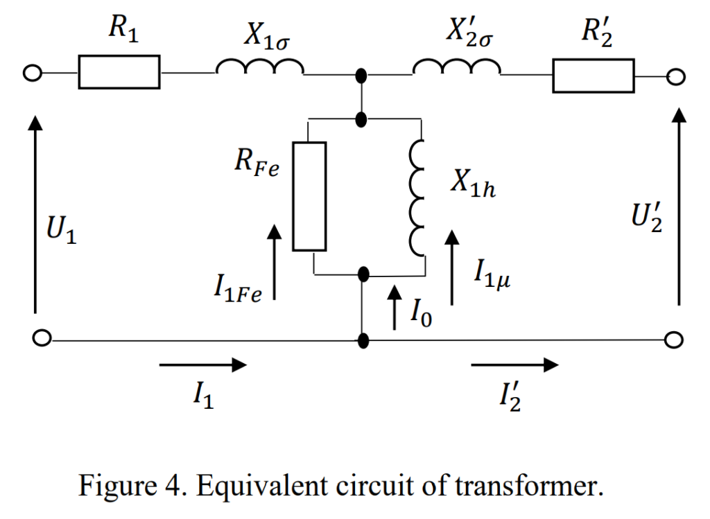
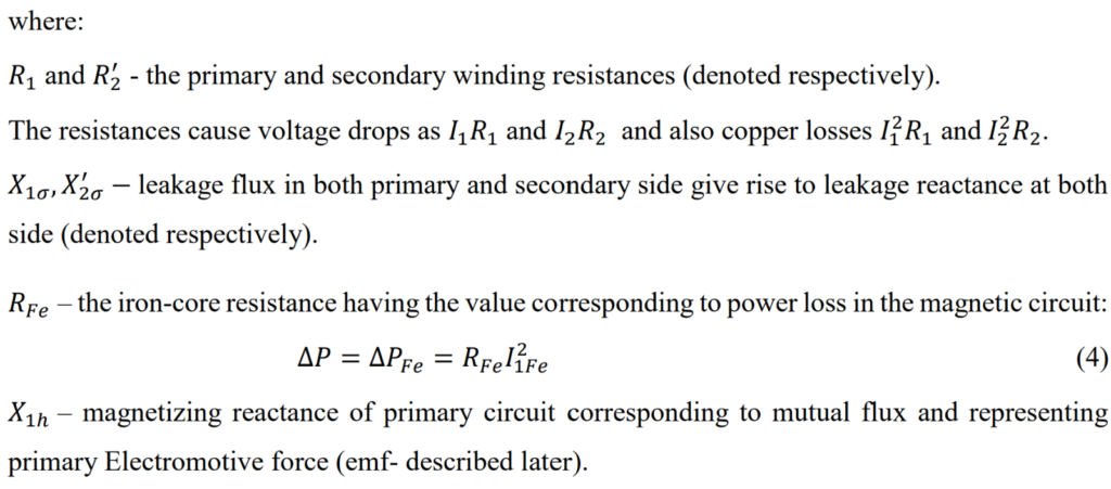
Figure 5 provides a simplified representation of the transformer’s impedance (Z), combining both reactance and resistance. Let’s describe the operation of the transformer using easy-to-understand words based on this reduced circuit.
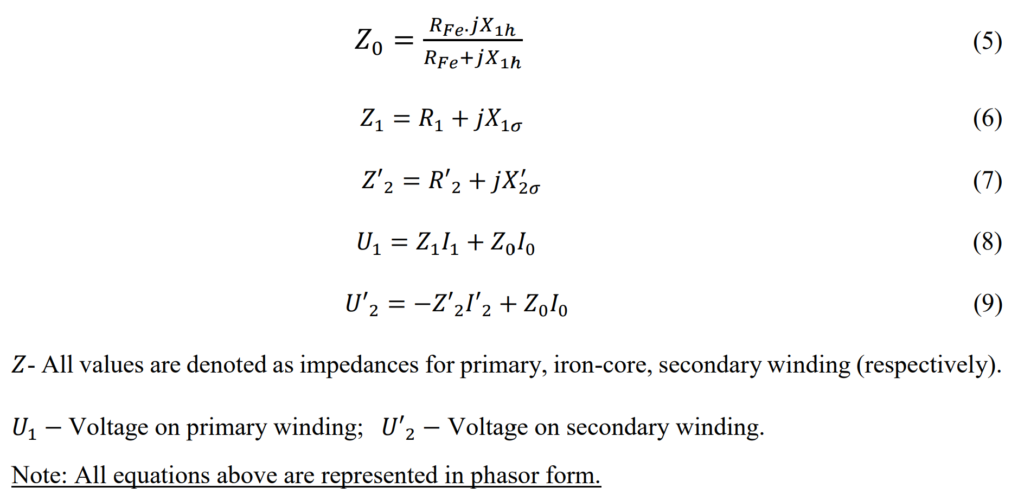
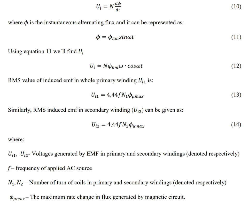
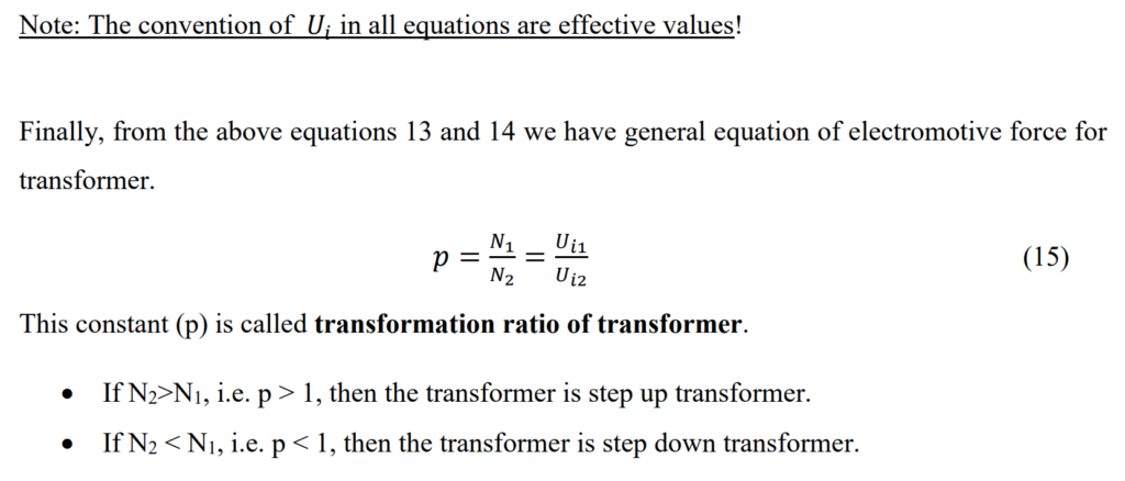
Electromotive force in windings
The electromotive force (EMF) equation of a power transformer can be derived based on Faraday’s law of electromagnetic induction. The EMF induced in a coil is proportional to the rate of change of magnetic flux linking the coil. In the case of a power transformer, the alternating current in the primary winding creates an alternating magnetic flux in the transformer core, which then links both the primary and secondary windings. This phenomenon can be described by the following equations:
Short-circuit state and short-circuit test
The short-circuit test is an essential method to determine the copper losses in a power transformer at full load and to obtain parameters for an approximate equivalent circuit. Let me summarize the key points:
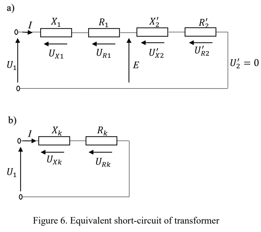
- The secondary terminals of the transformer are short-circuited (U2=0).
- Currents I2 and I1 can be very high, depending on the applied voltage.
I2 and I1 are significantly higher than the no-load current (I0), and for simplification, I0 is often assumed to be negligible (I0≈0).
With I0 approximated to zero, the equivalent circuit can be simplified.
Rk=R1+R2′
Xk=X1+X2′
Zk=Rk+jXk
Zk=U1/I
Where:
- Rk is the short-circuit resistance.
- Xk is the short-circuit reactance.
- Zk is the short-circuit impedance.
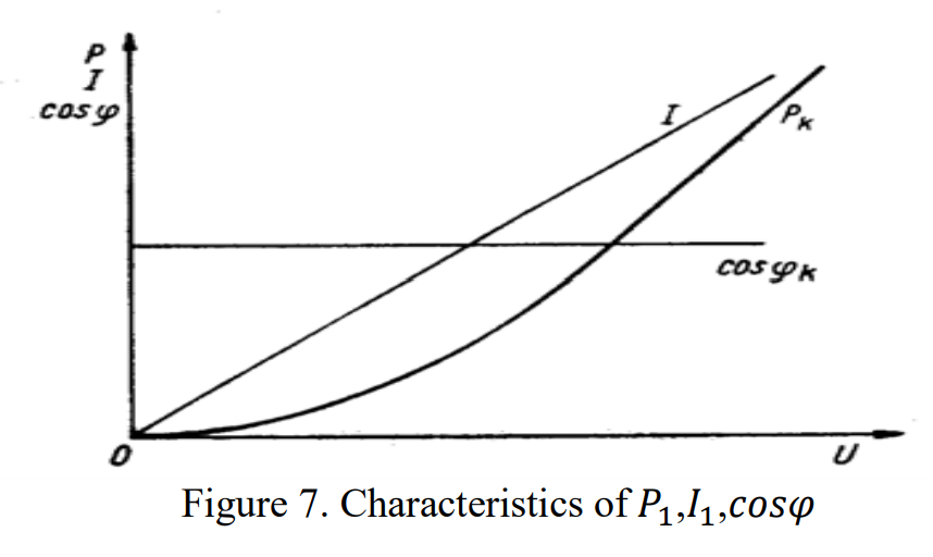
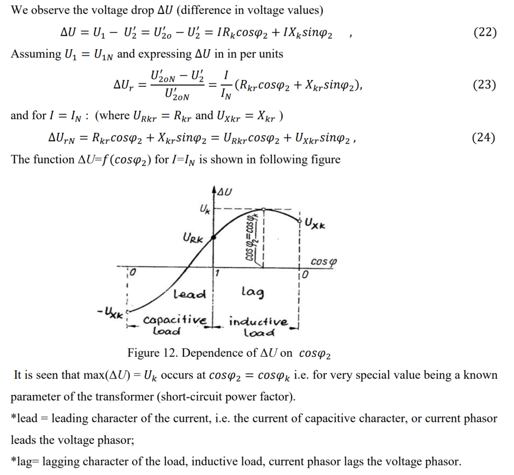
In laboratories or during field tests, short-circuit tests are commonly conducted on transformers. These tests involve gradually increasing the voltage from zero until it reaches a level that results in a current flow not significantly higher than the nominated current (IN). During this process, various parameters such as power (P1), current (I1), and power factor (cosϕ) are measured. The results are then used to create a graphical representation or characteristics plot.
When the primary current ((I_1)) in a transformer is at its nominated value ((I_N)), certain parameters are determined and specified during a short-circuit test:
- Short-Circuit Voltage ((U)):
- (U) represents the short-circuit voltage, and it has two components: (U_{Rk}) (short-circuit resistance voltage) and (U_{Xk}) (short-circuit reactance voltage). These components make up the total short-circuit voltage.
- Short-Circuit Power ((P_1)):
- (P_1) is the short-circuit power, indicating the power absorbed by the short-circuited transformer during the test.
- Short-Circuit Power Factor ((\cos \phi)):
- (\cos \phi) is the power factor during the short-circuit test ((\phi_k)). It reflects the phase relationship between the voltage and current during this condition.
The short-circuit voltage is a critical value. It is the supplied voltage to the short-circuited transformer that allows the flow of rated currents ((I_2) and (I_1)). This value is typically provided in transformer ratings or on nameplates, often expressed in per unit (p.u.) or percentage (%).
Typical percentage values for short-circuit voltage are:
- Several percent for small and medium power transformers.
- 10 to 20% for large power transformers, especially those with high capacities (hundreds of MVA).
During the short-circuit test, the power absorbed by the transformer ((P_1)) is considered as “lost” power since the output power ((P_2)) is zero. It’s important to note that iron losses in the transformer during a short circuit are relatively smaller compared to copper losses and can be neglected for practical purposes.
No-load operation and no-load test
When a power transformer is in a no-load state, it means the secondary circuit is open: (I_2) is zero, and (I_1) equals the nominated current ((I_N)). Conducting a no-load test on the transformer is straightforward, whether in a laboratory or at a substation.
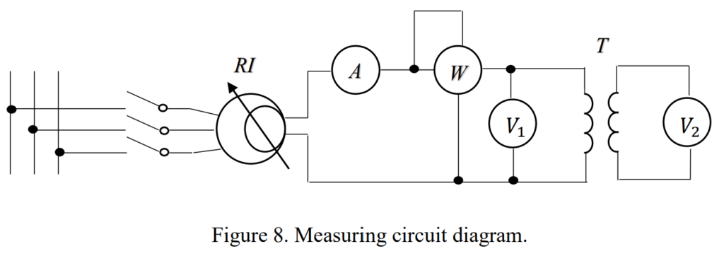
In the test setup, you have an RI (induction regulator) acting as a variable voltage source, an ammeter (A), a voltmeter (V), and a wattmeter (W). During the test, the input voltage is adjusted, ranging from 0 up to (UN) (and sometimes even higher). The test involves measuring the following quantities: (U1) (primary voltage), (U2) (secondary voltage), (I0) (no-load current), and (P1) (power).
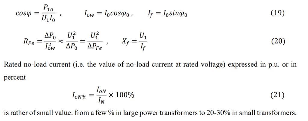
where ,
– magnetizing current (reactive component of no-load current
0 – no-load current
– active component of no-load current
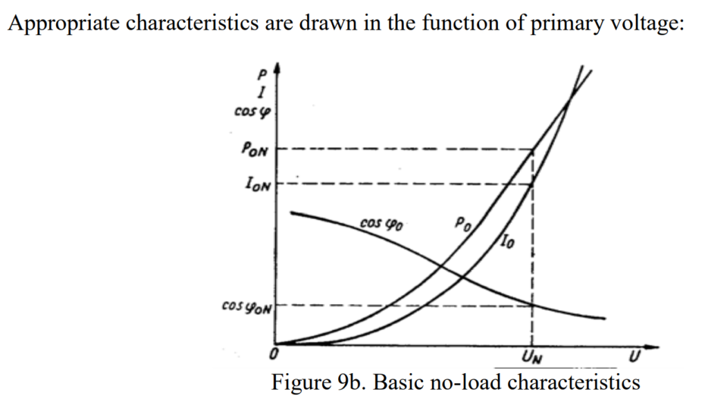
From the no-load test results, we can determine some parameters of the transformer being tested
or its equivalent circuit:
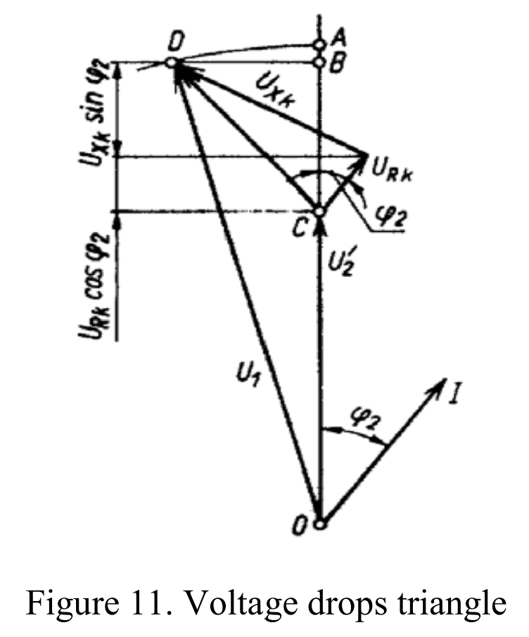
Under load state
In simplified consideration of transformer operation under load, we use a simplified equivalent circuit. Although this simplification introduces some error, it’s generally acceptable when the no-load current (I0) is much smaller than the load currents (I1 or I2). Therefore, we can apply this equivalent circuit for discussing fully loaded power transformers.
With this simplified model, we can analyze the variation in output voltage for different values and characteristics of the load current. Let’s consider a specific scenario: the transformer is supplied with a constant primary voltage U1, and the loading current I2 varies. The nature of the load current is defined by its phase angle ϕ2, which changes within a closed interval [-90°, +90°].
When I′2=I=0, the output voltage U2′o=U1. As I>0 and for certain ϕ2,U2o is the no-load output voltage, and it differs from U1 when U1 ≠U1N. This means that as the load current increases, the output voltage of the transformer can vary based on the phase angle and the constant primary voltage supplied.
Types of Transformers
Let’s simplify and summarize the types of transformers based on their usages, shapes, and characteristics:
- Step-Up and Step-Down Transformers:
- Used for adjusting voltage levels in power transmission and distribution networks.
- Three-Phase and Single-Phase Transformers:
- Three-phase transformers are commonly used in three-phase power systems due to cost-effectiveness. However, for ease of transportation, banks of three single-phase transformers are preferred in certain situations.
- Power and Distribution Transformers:
- Power Transformers transfer energy between high and very high voltage systems, operating during high loads. Distribution Transformers step down voltage for distribution to homes and businesses, operating efficiently at 50% of full load.
- Indoor and Outdoor Transformers:
- Indoor transformers are designed for installation indoors, while outdoor transformers are meant for outdoor installation.
- Oil-Cooled and Dry-Type Transformers:
- Oil-cooled transformers use transformer oil for cooling, whereas dry-type transformers use air as the cooling medium, eliminating the need for oil.
- Phase-Shifting Transformers:
- Control power flow in complex power transmission networks by:
- Regulating power flow between independent power systems.
- Adjusting the phase displacement between input and output voltages, controlling active power flow in transmission lines.
These transformer types cater to various needs in power systems, ensuring efficient energy transfer, voltage adjustment, and control in different applications.
Power Transformer in Transmission and Distribution systems
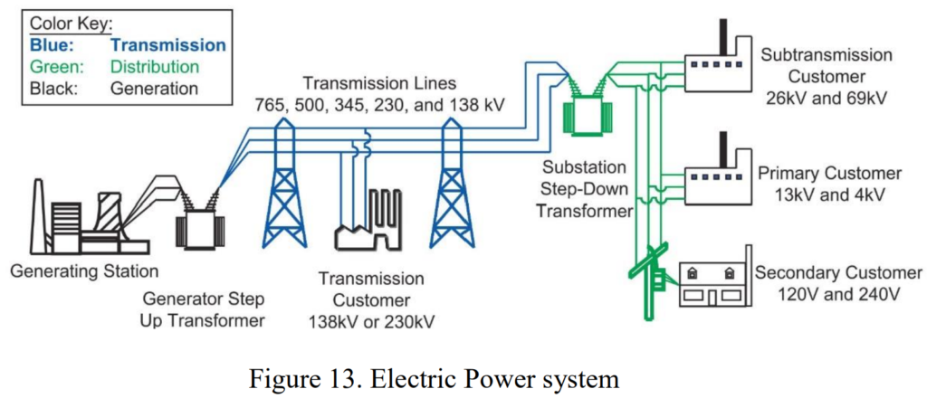
Transmission and distribution systems play crucial roles in the efficient supply of electrical power from generation sources to end-users. The distinction between these systems lies in their scale, voltage levels, and operational characteristics.
Transmission:
Transmission is the process of bulk power transfer at high voltages between central power generation stations and load centers. The efficiency of modern transformers used in transmission systems is impressively high, ranging from 90% to 99%. Generators typically produce voltages in the range of 11–25kV, which are then increased by transformers to the main transmission voltage. Substations play a key role in the transmission network, facilitating the connection and switching of various components such as lines and transformers. Large amounts of power, often at high voltages like 400kV or 765kV in the USA, are transmitted from generating stations to load centers.
Distribution:
Distribution, on the other hand, involves delivering power to consumers through lower voltage networks. Distribution transformers, responsible for the final step into consumer mains voltage, are designed to be highly efficient. Distribution networks differ from transmission networks in terms of structure and voltage levels. They include components like step-down transformers at bulk supply points and a network of transformers supplying consumers at varying voltages (e.g., 240V in Europe, 110V in the USA). Distribution transformers, owned by electricity distribution companies, supply about 70% of low voltage electricity to end-users.
Voltage Levels Classification:
The classification of voltage levels in power systems is crucial for understanding the operational characteristics of transformers. These levels include:
- Extra High Voltage: Typically used in the transmission grid (>150kV), ranging from 220–400kV (ultra-high >400kV).
- High Voltage: Ranges from >70 kV up to 150 kV.
- Medium Voltage: Ranges from >1 kV up to 70 kV, typically up to 36 kV.
- Low Voltage: Below 1kV, including common values like 110V, 240V, and 690V.
In essence, the transmission and distribution systems work together to ensure a reliable and efficient supply of electrical power, with transformers serving as key components in adjusting voltage levels for different operational requirements.
Special types of transformers
Instrument transformers
An instrument transformer is an essential electrical device designed to transform current and voltage levels. It is often referred to as an isolation transformer because it provides a safe way to handle high current and high voltage in electrical systems. The primary purpose is to safeguard measuring instruments, relays, and energy meters connected to its secondary side from potential damage.
Current Transformer (CT)
A Current Transformer (CT) is a vital tool in electricity. It does two main jobs: measuring current and protecting the system. Imagine it like a magic device that helps understand and control the flow of electric current. The CT has a simple setup: a primary side with just one turn (or a few) where the current flows, and a secondary side with lots of turns wound around a special core. This setup allows the CT to safely measure and reduce the current, making it easier to keep track of and protect the electrical system. In essence, the CT ensures the right amount of current is flowing, keeping everything in check and preventing potential issues.
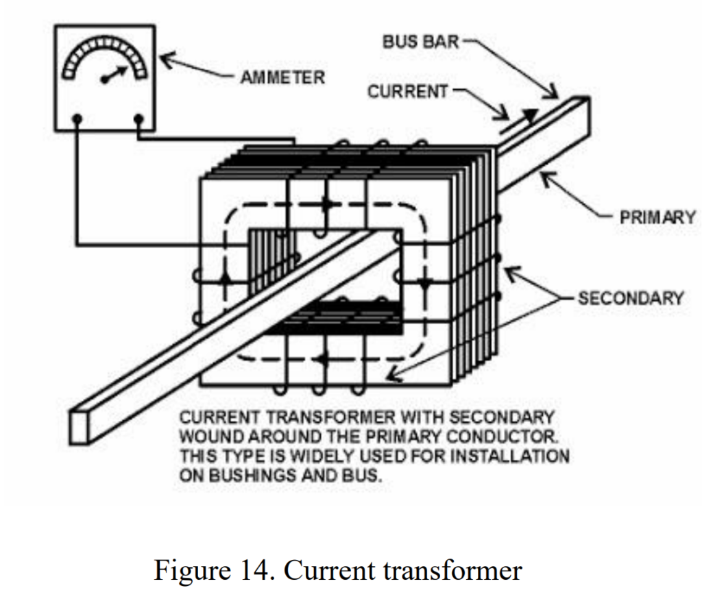
A Current Transformer (CT) is identified by its current ratio, like 2000:5, which means it produces 5 amperes on the output when 2000 amperes flow in its primary winding. Think of it as a translator for electric currents. CTs are buddies with various instruments like ammeters, wattmeters, and more. They work with protective relays and circuit breakers to keep electrical systems safe. It’s cool that one CT can work with multiple instruments, as long as the combined load doesn’t go over its limit. The secondary winding of a CT is usually rated at 5 amperes, making it a handy tool for various electrical measurements.
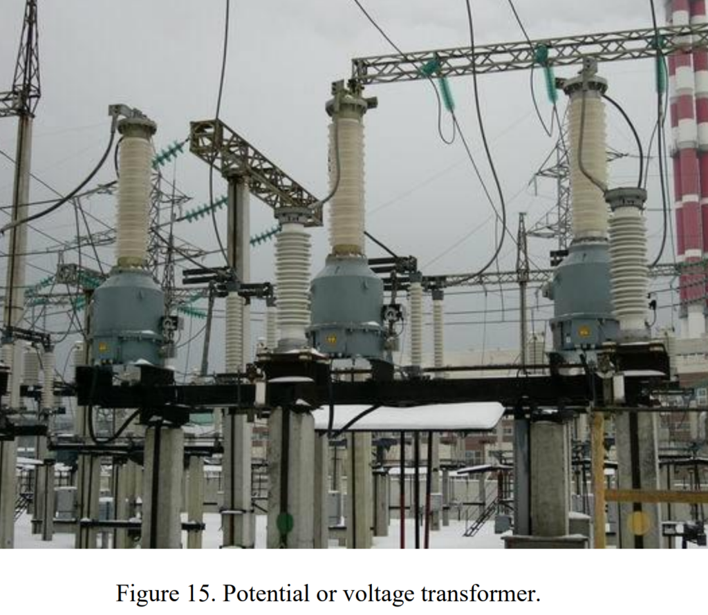
Potential Transformers (PT)
A Potential Transformer (PT), also known as a voltage transformer, is like a wizard for managing voltage levels. Its primary job is to safely step down high voltages to a manageable level. PTs are buddies with instruments like voltmeters, wattmeters, and more. They play a crucial role in measuring power factors, frequencies, and synchronizing devices, as well as working with protective relays and circuit breakers’ trip coils for voltage control. What’s neat is that one PT can team up with multiple instruments, as long as the total power they need doesn’t exceed the transformer’s capacity. So, PTs are like the guardians of safe voltage levels in the electrical realm.
Autotransformers
An Autotransformer is a special kind of transformer featuring just one winding on a laminated core. They are a more cost-effective and compact option for making small voltage adjustments compared to standard transformers. Autotransformers efficiently transfer power through a wire connection, with a significant portion passing through the main winding.
In this type of transformer, less current flows through the auxiliary shunt winding, while the majority travels through the series winding, which has a lower voltage. Autotransformers find primary use in distribution systems for two main applications:
- Voltage Regulators:
- Autotransformers equipped with adjustable taps act as voltage regulators. They can fine-tune voltage levels, typically within a range of ± 10%, ensuring stable power supply.
- Step Banks:
- Autotransformers are commonly used in place of traditional transformers in step banks and even substation transformers. They are particularly effective when a moderate change in relative voltage is required.
In summary, Autotransformers offer a practical and cost-efficient solution for voltage adjustments, with applications ranging from regulating voltage on distribution systems to facilitating moderate changes in substation transformers.
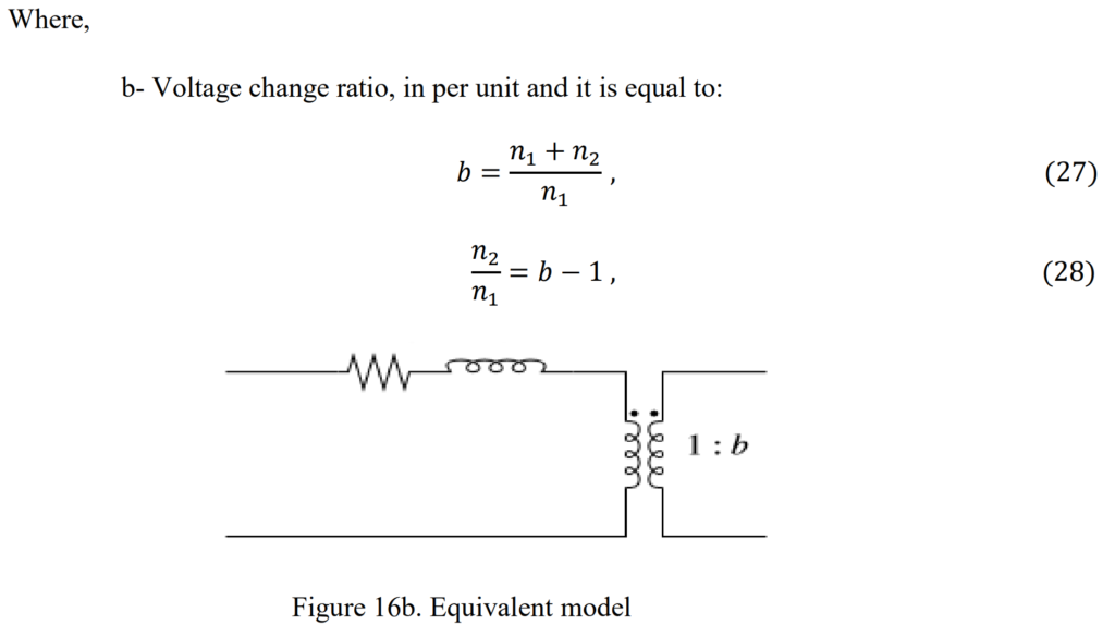
The rating of an autotransformer is determined by the voltage change between its primary and secondary windings. This rating is expressed as a percentage of the load, denoted by “b” in the formula:
S=b−1/b
For example, achieving a 10% voltage change (b = 1.1) requires an autotransformer to be rated at only 9% of the load kVA. Similarly, for a 2:1 voltage change (b = 2), the autotransformer needs to be rated at 50% of the load kVA. In contrast, a standard transformer must have a kVA rating equal to the load kVA.
Autotransformers exhibit lower series impedance compared to equivalent standard transformers. The equivalent series impedance Zauto of the autotransformer is calculated using the formula:
Zauto=(b−1/b)2×Z
Here, Z represents the impedance across the entire winding. This characteristic makes autotransformers advantageous in terms of impedance when compared to standard transformers.
Power Transformer Taps
Power Transformer taps play a crucial role in adjusting the output voltage of power transformers. These taps, situated on the primary or secondary windings, allow for changes in the number of turns, thus influencing the output voltage. The method of tap adjustment varies for different types of transformers.
In oil-cooled transformers, taps are connected to an oil-filled tap changer, either externally located or within the oil tank. On the other hand, dry-type transformers have taps linked to insulated terminal boards inside the metal housing, accessible by removing a panel.
The decision on whether to place taps on the primary or secondary side depends on several factors. These include the transformer’s current rating, insulation levels, winding type (e.g., star, delta, autotransformer), position of the tap changer in the winding, cost considerations, and physical size.
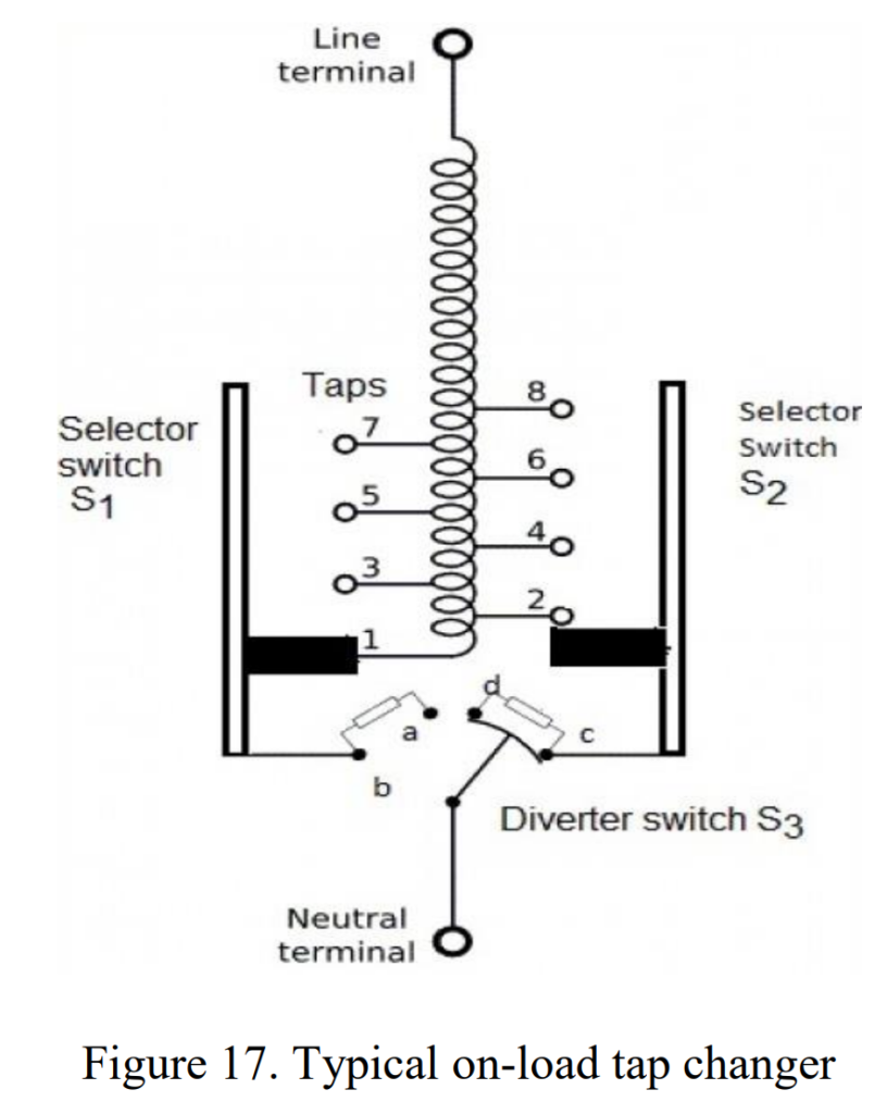
Tap changers are categorized into two main types: On-Load (OLTC) and Off-Load/De-Energized (DECT). Off-load tap-changing mechanisms require isolating the power transformer before adjusting tap settings, commonly found in smaller distribution transformers. However, due to interruptions in the power supply caused by off-load tap changers, on-load tap changers have become the preferred choice in modern power systems.
On-load tap changers permit the adjustment of taps while the power transformer is actively in service. They consist of a diverter switch and a selector switch working together to transfer current between voltage taps. The diverter switch includes resistors with typical values of a few ohms.
In summary, tap changers offer a flexible means to adjust voltage settings in transformers, with on-load tap changers being more favored for their ability to make changes without interrupting the power supply.
Power Transformer connections
Three-phase transformer connections
When establishing three-phase connections, there are two primary approaches: utilizing three single-phase transformers or opting for a three-phase transformer. The latter, employing a three-phase transformer, presents several advantages. Firstly, it proves to be more cost-efficient than using three separate single-phase transformers. Additionally, the overall weight of a three-phase power transformer is less, facilitating easier handling and installation. Moreover, it requires less floor space, making it a space-efficient solution for various applications. Importantly, three-phase transformers generally exhibit lower losses compared to the arrangement of three single-phase transformers.
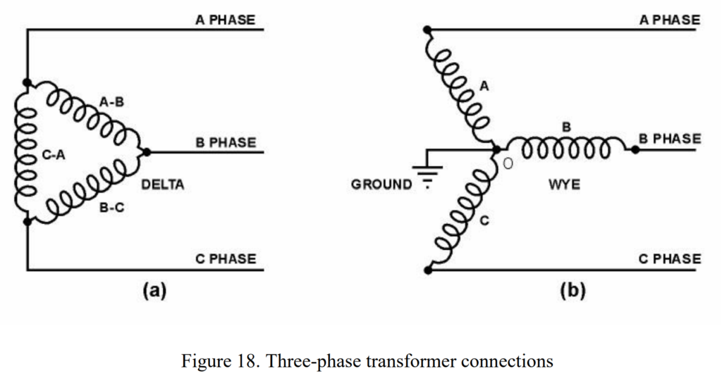
Regardless of the chosen method, whether a three-phase transformer or three separate single-phase transformers, the methods of connecting windings remain consistent. Figure 18 illustrates the two primary methods of connecting three-phase transformers.
In the Delta Connection method (Figure 18a), the windings are connected in a delta configuration. On the other hand, the Star or Wye Connection method (Figure 18b) involves connecting the windings in a star or wye configuration. A noteworthy difference between the wye and delta connections is that the wye connection has two phases in series. The common point “O” of the three windings is designated as the neutral point in a wye connection, with equal voltages existing between this neutral point and any of the three phases.
In summary, both connection methods have their applications, but the three-phase transformer offers advantages in terms of cost, weight, floor space, and losses compared to using three separate single-phase transformers.
Wye–Wye Connections of Transformer
In high-voltage transmission systems, the utilization of the wye-connected transformer proves to be more economical. This is attributed to the fact that the voltage across the phase of each winding is 1.73 times less than the voltage between the lines. If the neutral point is grounded, it eliminates the need for insulation at the line voltage.
Figure 19 depicts a bank of three transformers connected in a Y (wye) configuration on both the primary and secondary sides. If the transformation ratio of each transformer is denoted as K, the same ratio will exist between the line voltages on both sides. However, it’s crucial to note that this connection is most effective when the three-phase load is balanced. Any imbalance in the load can cause the electrical neutral to shift from its exact center, resulting in unequal line-to-neutral voltages.
Advantages of the Y-Y connection include the alignment of primary and secondary circuits in phase. This lack of phase angle displacements is especially advantageous when transformers are used to interconnect systems of different voltages in a cascading manner. For instance, a series of Y-Y transformer connections can efficiently interconnect systems operating at 500, 230, 138, and 69kV.
Another advantage is that if the neutral end of a Y-connected winding is grounded, reduced levels of insulation can be used at the neutral end, compared to a winding connected across the phases, which requires full insulation throughout.
However, there are disadvantages to the Y-Y connection. The presence of third (and other zero-sequence) harmonics at an ungrounded neutral can lead to overvoltage conditions, particularly at light load. When constructing a Y-Y transformer using single-phase transformers connected in a bank, the measured line-to-neutral voltages are not 57.7% of the system phase-to-phase voltage at no load but are about 68%, decreasing rapidly as the bank is loaded. The effective values of voltages at different frequencies combine by taking the square root of the sum of the voltages squared, and this needs consideration, especially when dealing with harmonic components.

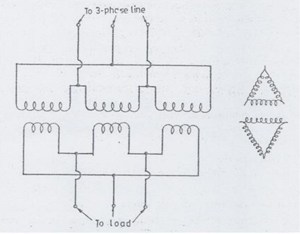
Delta–Delta Connection
The delta-delta connection offers economic advantages over the wye-wye connection, especially in scenarios requiring low-voltage and high-current applications. In this configuration, the winding current is reduced by a factor of 1.73, amounting to 58% of that in the wye-wye connection. Additionally, the delta-delta connection provides operational flexibility when composed of three single-phase transformers. If one transformer fails, it can be switched out of the line, allowing the remaining two phases to operate at 86.6% of their rating in the open delta configuration. This capability ensures continued operation at a reduced power level in case of a power transformer failure.
However, the delta-delta connection comes with a notable disadvantage: the absence of a neutral point. Without a neutral point, the phases cannot be grounded except at the corners. This limitation leads to higher ground voltages during system faults or transient voltages, making the insulation design more costly. To address this issue, supplying an artificial neutral to the system with a grounding transformer can help control these voltages. It’s important to note that the insulation costs for the delta-delta connection increase with rising voltage levels. Consequently, this type of connection is typically limited to a maximum system voltage of 345 kV. Figure 20 illustrates a bank of transformers connected in a delta configuration on both the primary and secondary sides.
Wye–Delta and Delta–Wye Connections
The wye-delta or delta-wye connections stand out as having fewer objectionable features compared to other transformer connections. These configurations effectively combine the advantages of both wye-wye and delta-delta connections. The presence of the delta ensures complete voltage and current symmetry. The exciting third-harmonic current circulates within the delta winding, preventing any third-harmonic voltage from appearing in the phase voltages on the wye side. This allows for high-voltage windings to be connected wye, and the neutral can be brought out for grounding, minimizing insulation costs.
To regulate differences in magnetizing current, voltage ratio, or impedance between the single-phase units, a small circulating current in the delta is employed. However, this leads to unbalanced phase voltages on the delta, causing a circulating current within it.
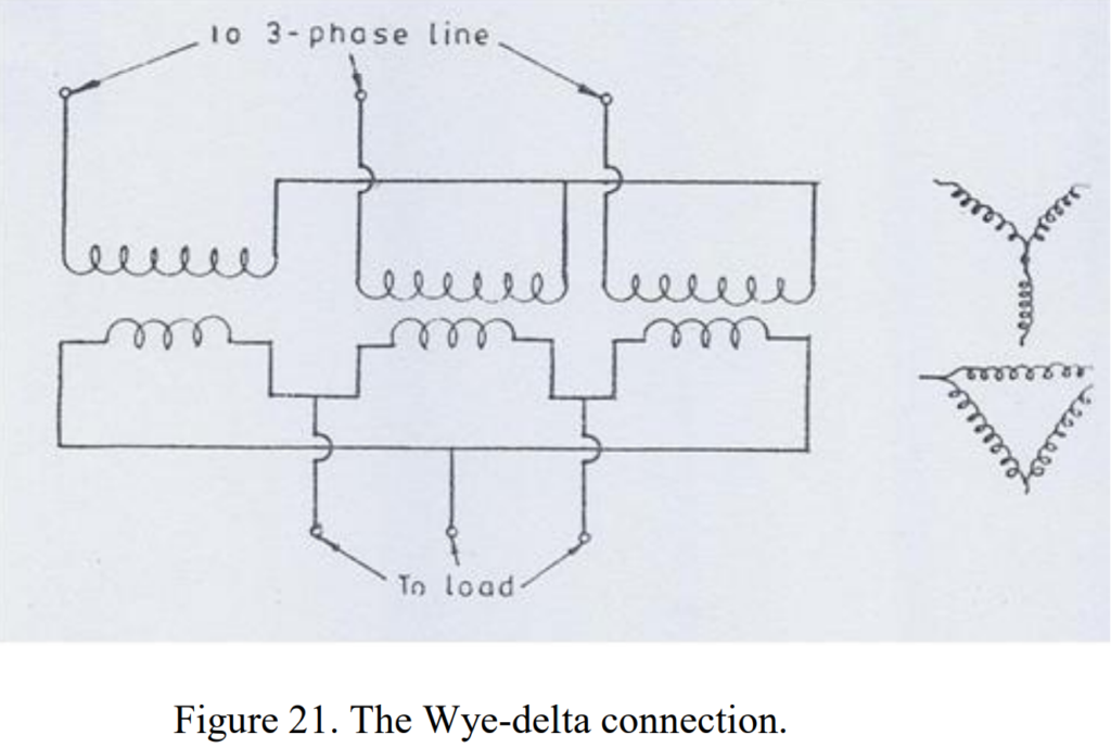
Despite its many advantages, the delta-wye connection does have some disadvantages. Notably, it introduces a 30-degree phase shift between the primary and secondary windings, requiring careful matching for parallel operation. In emergency situations, a delta-wye bank cannot be operated with only two phases. If the delta is on the primary side and accidentally opens, the unexcited leg on the wye side can resonate with the line capacitance.
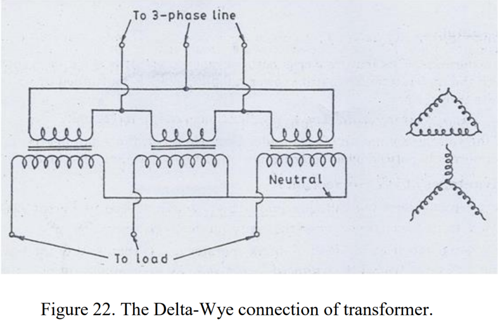
The three-phase Delta-Wye connections are depicted in Figure 22, commonly employed where there’s a need to step up the voltage, such as at the beginning of a high-tension transmission system.
Technical aspects of transformers
Power Transformer cooling
The efficiency of power transformer is typically more than 99%, resulting in nearly equal input and output powers. Despite this high efficiency, some losses occur within the transformer due to factors like conductor losses, losses in electrical steel caused by changing flux, and losses in metallic structures due to stray time-varying flux. These losses lead to temperature increases, necessitating effective cooling methods.
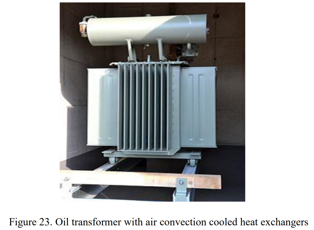
Oil-cooled transformers immerse coils and cores in an oil-filled tank, with the oil circulated through radiators or heat exchangers, ultimately dissipating heat to the surrounding air or water. In small distribution transformers, radiators may not be needed, as the tank surface provides sufficient cooling, often augmented by fins or corrugations.
The choice of cooling medium depends on factors like dielectric strength, safety considerations, and environmental impact. Oil immersion is common in higher voltage transformers due to its higher breakdown strength, with natural convection providing cooling. Air-cooled units, where air is blown through the windings with fans, are more efficient and suitable for units inside buildings, reducing the fire hazard. The flash point of power transformer oil is high, and safety measures, such as sealing the tank or using inert gases like nitrogen, minimize the risk of fires.
Environmental considerations also influence coolant choices. While mineral oil used in transformers poses environmental risks, air-cooling is preferred for applications with transport restrictions, such as planes or trains. Oil-cooled transformers, using standard or specialized oils like silicon oil, find widespread use in various applications, from large generators and substations to distribution units on telephone poles. Sulfur hexafluoride gas, with higher breakdown strength, is used in high-voltage units where oil is unsuitable and air lacks sufficient dielectric strength.
Transformer Cooling Methods
Dry Type Transformers: Air Natural (AN) and Air Forced (AF)
Dry type transformers utilize air as the cooling medium and are classified into two types: Air Natural (AN) and Air Forced (AF).
1. Air Natural (AN):
- Usage: AN transformers are typically employed for small rating transformers, generally up to 3 MVA (Mega Volt-Ampere).
- Cooling Mechanism: This method relies on the natural airflow in the surroundings of the transformer for cooling.
- Application: Suited for smaller transformers where the heat dissipation is effectively managed by the natural convection of air.
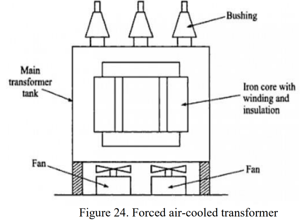
2. Air Forced (AF):
- Usage: AF transformers are used for transformers rated more than 3 MVA, where natural air-cooling alone is insufficient.
- Cooling Mechanism: Blowers or fans are incorporated to force air over the core and windings, enhancing the cooling process. This forced air circulation helps dissipate heat more efficiently.
- Application: Effective for transformers up to 15 MVA, providing additional cooling power to handle higher loads.
- Maintenance: The air forced through the power transformer must be filtered to prevent the accumulation of dust particles in the ventilation ducts, ensuring optimal performance.
Oil immersed transformers
Oil-immersed transformers utilize mineral oil as both an electrical insulator and a cooling medium for the transformer winding and core. This method is categorized into four types:
1. Oil Natural Air Natural (ONAN):
- Usage: Suitable for transformers up to approximately 30 MVA.
- Cooling Mechanism: Heat generated in the core and winding is transferred to the oil, which circulates naturally through convection. The heated oil rises, flows from the upper portion of the power transformer tank, and dissipates heat into the atmosphere through natural air flow.
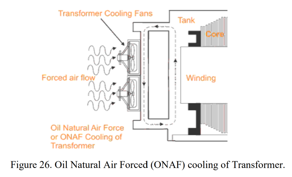
2. Oil Natural Air Forced (ONAF):
- Usage: Effective for large transformers, typically up to about 60 MVA.
- Cooling Mechanism: Combines natural oil circulation with forced air cooling. Fans are used to enhance heat dissipation, resulting in a faster cooling rate compared to ONAN. Fans automatically start when the temperature exceeds a certain value.
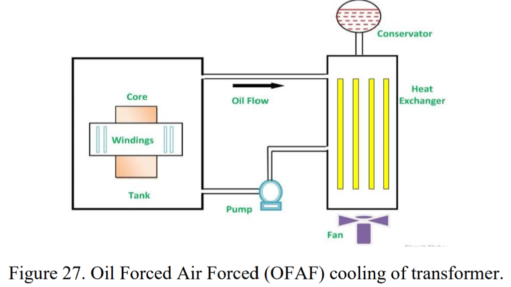
3. Oil Forced Air Forced (OFAF):
- Usage: Applied to higher rating transformers at substations or power stations.
- Cooling Mechanism: Oil circulation is facilitated by a pump, and compressed air is forced to pass through the heat exchanger with high-speed fans. Heat exchangers can be located separately from the transformer tank, connected through pipes.
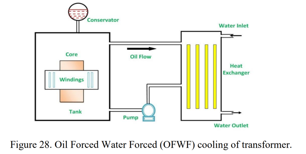
4. Oil Forced Water Forced (OFWF):
- Usage: Commonly used for very large transformers with power ratings above 500 MVA.
- Cooling Mechanism: Oil is pumped through a heat exchanger, where it dissipates heat into water. The heated water is directed to external coolers for efficient cooling. Water, being a more effective heat exchanger medium than air, allows for cooling large transformers with high power ratings.
Each cooling method offers varying degrees of efficiency, making them suitable for transformers of different sizes and power requirements. The choice depends on factors such as transformer size, power rating, and the need for enhanced cooling capabilities. The accompanying figures illustrate examples of oil natural air natural and oil forced air forced cooling methods.
Losses in Power Transformer
Transformers, integral to power systems, are not exempt from energy losses inherent in their operation. Unlike machines with moving parts, transformers lack mechanical losses but still encounter various types of losses during their functioning. Let’s delve into the classifications of transformer losses:
No-load losses
No-Load Losses in Transformers: A Deeper Look
No-load losses, also known as iron losses or core losses, are a constant aspect of transformer operation, persisting 24/7, 365 days a year, irrespective of the load. Let’s delve into the components and characteristics of these losses:
- Hysteresis Losses:
- Nature: Result from the frictional movement of magnetic domains within the core laminations, experiencing magnetization and demagnetization with alternating magnetic fields.
- Contribution: Account for a substantial portion, ranging from 50% to 80%, of total no-load losses.
- Material Impact: The type of core material plays a crucial role; silicon steel exhibits lower hysteresis losses compared to normal steel, while amorphous metal showcases superior performance. Techniques like cold rolling, laser treatment, or grain orientation can reduce hysteresis losses.
- Eddy Current Losses:
- Cause: Induced by varying magnetic fields, resulting in the formation of eddy currents within the laminations, subsequently generating heat.
- Contribution: Typically responsible for 20–50% of total no-load losses.
- Mitigation: Constructing the core from thin laminated sheets, insulated by a thin varnish layer, helps reduce eddy currents and, consequently, eddy current losses.
- Stray and Dielectric Losses:
- Magnitude: Relatively less significant, contributing to no more than 1% of total no-load losses.
- Origin: Occur in the transformer core, presenting as stray and dielectric losses.
Understanding these components provides insights into the factors influencing no-load losses. Material selection, manufacturing processes, and design considerations all play crucial roles in optimizing transformers for reduced no-load losses and enhanced overall efficiency.
Load losses
Load Losses in Transformers: Unveiling Copper Losses
Load losses, also referred to as copper losses or short-circuit losses, emanate from the resistance encountered by the transformer winding during the transmission of load current. A comprehensive exploration of these losses encompasses the following aspects:
- Ohmic Heat Loss:
- Nature: Arises in transformer windings due to the inherent resistance of the conductor material.
- Dependency: The magnitude of this loss experiences a quadratic increase with the load current (²) and is directly proportional to the resistance of the winding ().
- Mitigation Strategies: Ohmic heat loss can be curtailed by augmenting the cross-sectional area of the conductor or by reducing the length of the winding conductor (=/).
- Conductor Eddy Current Losses:
- Cause: Induced by alternating current and manifest in the windings due to interacting magnetic fields.
- Reduction Tactics: Employing stranded conductors with individual strands isolated from each other helps control eddy current losses by diminishing the cross-section of the conductor.
Understanding these load losses is pivotal for optimizing power transformer design and operation. Balancing factors such as conductor geometry, material properties, and load characteristics allows for efficient management of copper losses, contributing to enhanced overall transformer performance.
Extra Losses in Transformers
In the realm of transformers, extra losses present a nuanced challenge, driven by factors such as unbalanced harmonics and reactive power. Delving into these phenomena provides a clearer understanding:
- Harmonics:
- Origins: Non-linear loads, typified by power electronics like variable speed drives, computers, and compact fluorescent lamps, induce harmonic currents in the network.
- Impact: Harmonic currents amplify both load and no-load losses due to heightened skin effect, eddy current, stray, and hysteresis losses.
- Source of Concern: Devices generating harmonic currents contribute to increased losses, necessitating attention to their impact on transformer efficiency.
- Unbalance:
- Transformation Behavior: Power Transformer encountering negative sequence voltages respond similarly to positive sequence voltages. The presence of a neutral conductor and the primary-secondary connections influence the behavior regarding homo-polar voltages.
- Potential Issue: Unbalance may lead to the flow of neutral current, particularly in configurations involving a three-phase four-wire connection on one side and a delta-connection on the other. This scenario can result in circulating currents, causing additional heat and losses in transformer components like the tank.
- Extra Losses Due to Current Distortion:
- Prominent Factor: Eddy current losses in the winding stand out as a significant consequence of current distortion.
- Frequency Impact: The impact of harmonic current on load loss is contingent on the harmonic frequency and power transformer design. Eddy current losses rise with the square of frequency and load current.
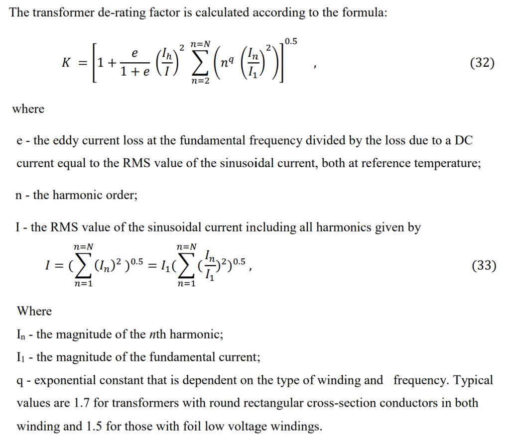
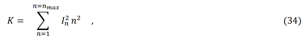
- Mitigation Strategies: To prevent overheating in transformers handling harmonic currents, derating—reducing the maximum apparent power transferred—is a common approach. In Europe, a de-rating parameter known as “factor K” estimates the required de-rating to align total harmonic load losses with the fundamental design loss.
Navigating these extra losses demands a holistic understanding of the transformer’s operating environment, ensuring optimal performance amidst dynamic load conditions.
b) Creating a special power transformer design for non-smooth load currents involves analyzing and reducing losses in the windings. This process includes calculating the temperature rise in critical areas, insulating individual laminations, and potentially increasing the size of the core or winding.
Manufacturers decide which techniques to use based on labor costs, production volume, and their equipment capabilities. These transformers, known as “K rated” transformers, are specifically designed to handle non-uniform loads. When selecting a transformer, designers should estimate the load’s K factor and choose a power transformer with an equal or higher K factor.
o Extra losses due to voltage distortion: The usual method mentioned earlier assumes that although the magnetizing current includes harmonics, these are very small compared to the load current, and their impact on losses is minimal.
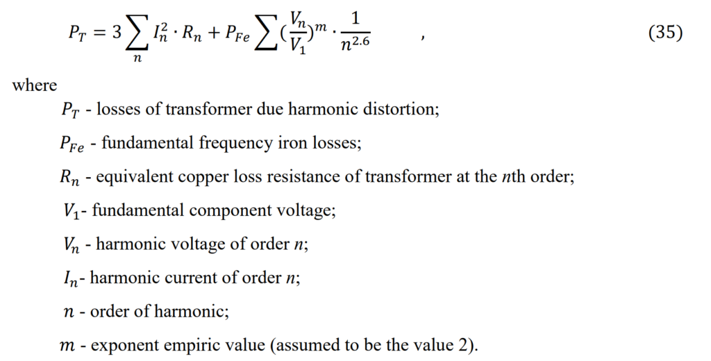
When considering additional harmonic losses caused by voltage harmonics and those generated in the transformer core, the complete formula for calculating losses in transformers due to harmonics is as follows:
Materials for manufacturing of transformers
Thanks to advanced data processing with mathematical tools and models, designing a power transformer now involves using the finite-element method. This approach considers electrical and mechanical strengths, heat transfer, and dynamic properties, including short-circuit conditions. It results in two-dimensional or three-dimensional field plots used to design various transformer elements, optimizing losses at desired levels with a balance between costs and efficiency.
Material and technology developments significantly impact losses in transformers. The evolution of material technologies is crucial for improving transformer efficiency. While fabrication techniques, such as better stacking, precision in manufacturing, and insulating against stray magnetic flux, contribute to smaller but meaningful loss reductions.
In terms of materials for the magnetic core, several options are available. Laminated steel, with thin iron sheets and insulating layers, is common for small to high-powered power transformers. Amorphous steel cores made from metallic tapes reduce eddy currents and are suitable for high-efficiency transformers. Ferrite ceramics are used in high-frequency applications, offering efficient insulation. Silicon steel, with high permeability and low losses, is used in high-performance applications. Vitreous metals, being non-crystalline, contribute to creating high-efficiency transformers.
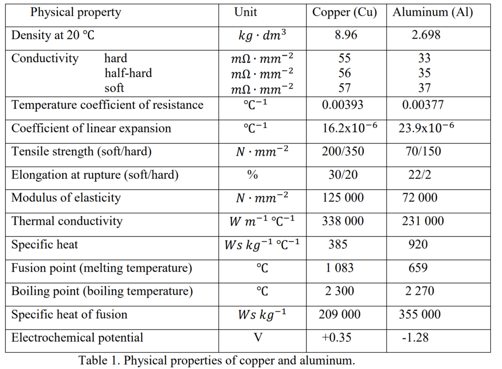
For winding materials, copper and aluminum are primary choices. While aluminum is lighter and cheaper, copper has higher mechanical strength and is predominantly used, especially in larger transformers. Stranded conductors with a rectangular cross-section are typical, although smaller transformers may use sheet or foil conductors. The choice between copper and aluminum often depends on factors like mechanical strength and final price.
The physical properties of copper and aluminum are shown in Table 1.
Practical problems in utilization of transformers
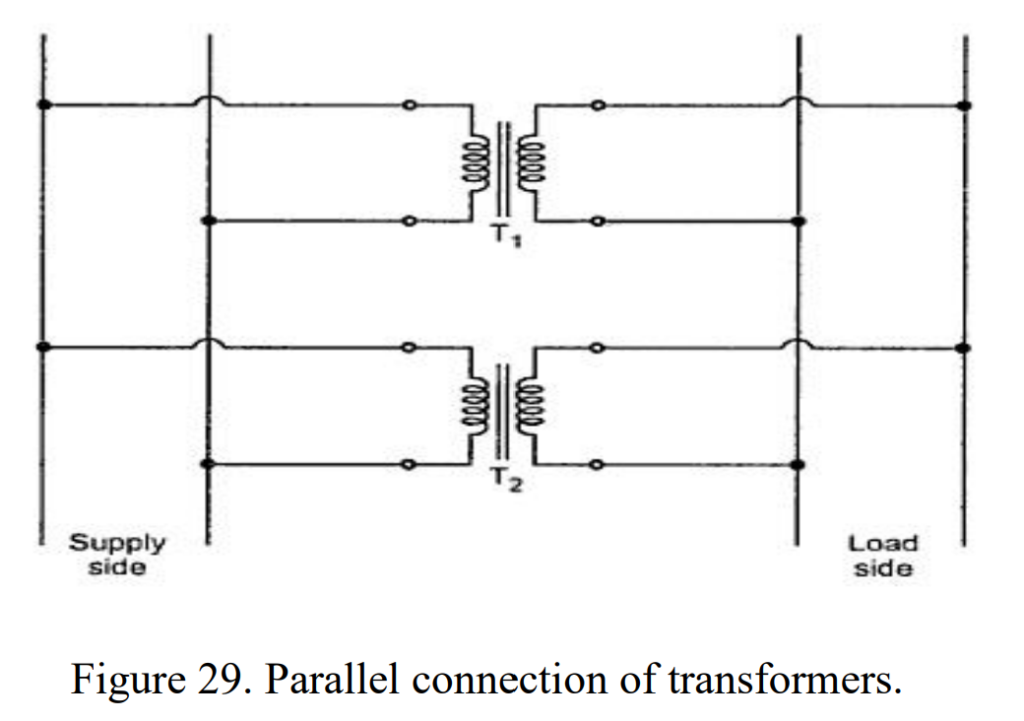
Parallel operation of transformers
Parallel operation of power transformers is a common practice employed when the load surpasses the rated capacity of an existing transformer. This approach involves connecting two or more transformers in parallel with the existing unit, offering increased reliability and cost-effectiveness compared to a single large transformer.
The decision to connect power transformers in parallel is often more economical than replacing an existing unit with a larger one. In a parallel setup with two transformers of equal rating, the cost of the spare unit is typically lower than that of a single larger transformer. Additionally, for enhanced reliability, having transformers in parallel is preferable.
Certain requirements must be met for the successful parallel operation of transformers:
- Same Voltage Ratio & Turns Ratio: Both primary and secondary voltage ratings must be identical.
- Same Percentage Impedance and X/R Ratio: The transformers should have matching impedance characteristics.
- Identical Position of Tap Changer: The tap changers in the transformers should be in the same position.
- Same KVA Ratings: Transformers should have the same kilovolt-ampere (KVA) ratings.
- Same Phase Angle Shift (Vector Group): Transformers should belong to the same vector group to maintain proper phase relationships.
- Same Frequency Rating: Transformers should operate at the same frequency.
- Same Polarity: Matching polarity is crucial for proper parallel operation.
- Same Phase Sequence: The transformers should have the same phase sequence to avoid issues in synchronization.
Meeting these requirements ensures a seamless parallel operation of transformers, contributing to improved system reliability and efficiency.
The use of parallel connection in transformers serves various important purposes within an electrical power system:
- Maximizing Electrical Power System Efficiency:
Power transformers exhibit optimal efficiency at full load. By running transformers in parallel, only the necessary units can be activated to meet the total demand, approaching full load during that time. This method ensures that the system operates with maximum efficiency. - Maximizing Electrical Power System Availability:
Parallel operation allows for the shutdown of individual transformers for maintenance purposes without completely interrupting power supply. The remaining parallel transformers continue to serve the load, ensuring continuous power availability. - Maximizing Power System Reliability:
In the event of a fault or trip in one of the power transformers running in parallel, the system redistributes the load among the remaining transformers. This prevents power supply interruptions as long as the shared loads do not overload the remaining transformers. - Maximizing Electrical Power System Flexibility:
Parallel connection provides flexibility to accommodate potential changes in future power demand. If there’s a projected increase in demand, connecting transformers in parallel can fulfill the extra demand without the need for a costly investment in a more powerful single transformer. Conversely, if future demand decreases, parallel transformers can be removed to balance capital investment and returns.
These purposes highlight the advantages of parallel connection in terms of efficiency, availability, reliability, and flexibility, making it a strategic choice in managing and optimizing power systems.
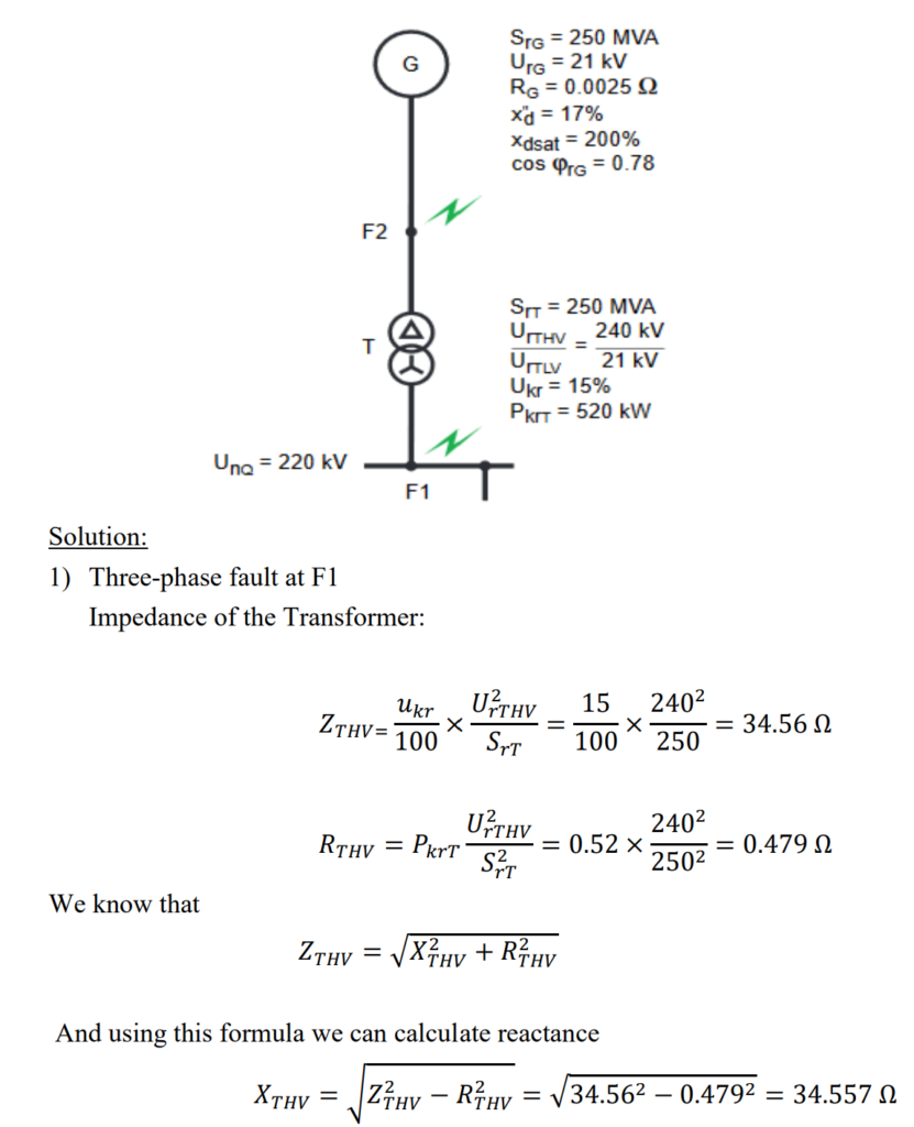
Calculation example for short-circuit level in Power Transformer
Power Station Unit S consists of a generator (G) and a transformer (T) equipped with an on-load tap changer.
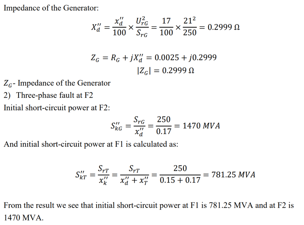
Calculate: The initial short-circuit power at F1 and F2 Impedances of the Transformer and Generator.
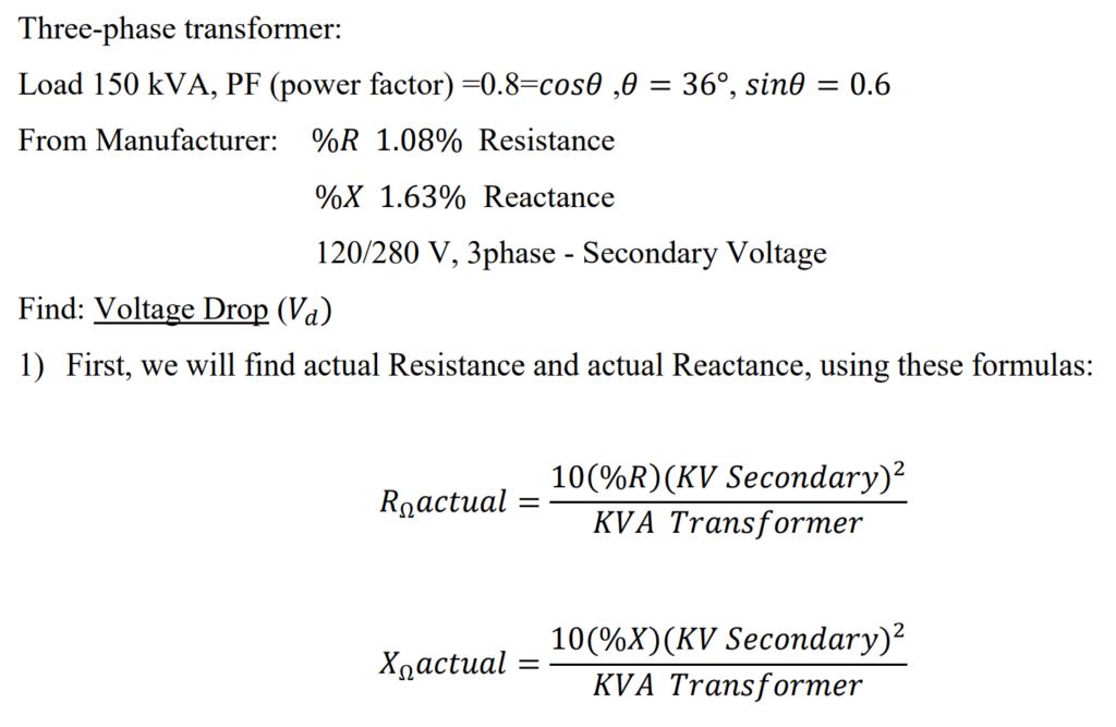
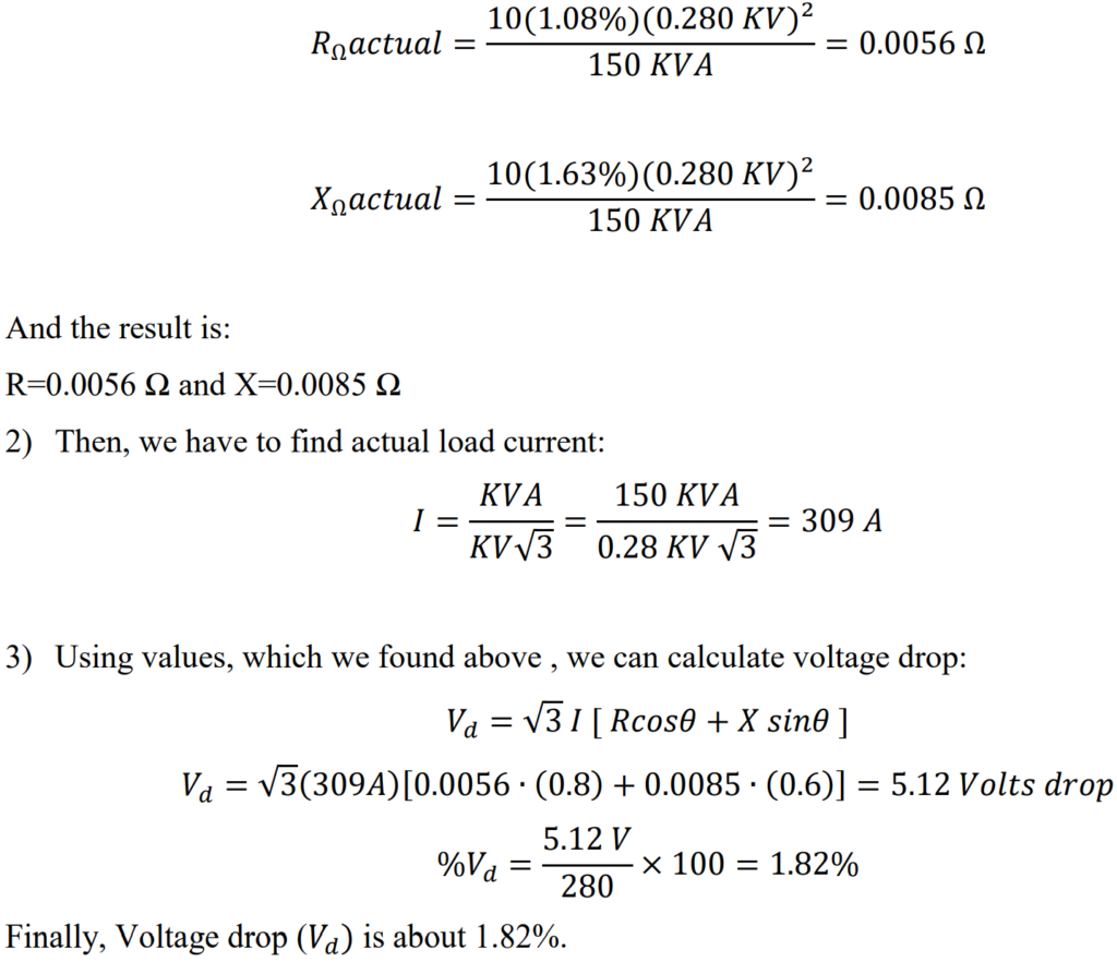
Voltage drop calculation in Power Transformer