An Inertial Navigation System (INS) is a navigation aid that uses a computer, motion sensors (accelerometers), rotation sensors (gyroscopes), and sometimes magnetic sensors (magnetometers) to track the position, orientation, and velocity of a moving object without the need for external references such as landmarks or GPS signals.
Inertial navigation is a way to figure out where something is and how it’s moving without needing help from outside sources like GPS. It works by using sensors called accelerometers and gyroscopes to keep track of how fast something is moving and in what direction.
What is Inertial Navigation System (INS)?
Inertial Navigation System Basic Explanation.
Imagine you’re driving a car. If you have a special device in the car called an Inertial Measurement Unit (IMU), it has tiny sensors inside that can tell how fast the car is going (accelerometers) and which way it’s turning (gyroscopes). By using these sensors, the device can figure out where the car is and which way it’s facing, starting from a known point.
So, even if you’re in a tunnel or a place where GPS doesn’t work well, the IMU can still help you know where you are and which way you’re going.
Inertial sensors are devices that measure both rotation rate and acceleration, and they treat these measurements as vectors. Gyroscopes specifically measure rotation: rate gyroscopes tell you how fast something is rotating, while integrating gyroscopes tell you the total angle of rotation.
Accelerometers, on the other hand, measure acceleration. However, it’s important to note that they can’t directly measure the acceleration due to gravity. This means that if you have an accelerometer in free fall, like in orbit around the Earth, it won’t register any acceleration.

Mathematically, we can represent the relationship between these measurements and other factors using equations like the one provided:
R=Rr+ dw/dt × R + 2w × dR/dt + w × (w×R) = A+g
In this equation:
- (R) represents rotation.
- (Rr) represents the rotation rate measured by gyroscopes.
- (dw/dt) represents the change in rotation rate over time.
- (w) represents the rotation vector.
- (dR/dt) represents the change in rotation over time.
- (A) represents acceleration measured by accelerometers.
- (g) represents gravitational acceleration.
This equation helps to illustrate how different measurements and factors contribute to the overall understanding of an object’s motion in space.
What is Inertial Measurement Units (IMU)?
Inertial navigation is a method of navigation that relies on sensors like accelerometers and gyroscopes to figure out where an object is and how it’s moving, relative to a starting point. In devices called Inertial Measurement Units (IMUs), there are usually three gyroscopes and three accelerometers, each measuring different aspects of motion. By analyzing the signals from these sensors, we can keep track of the object’s position and which way it’s facing.

This navigation technique is used in many different things like aircraft, missiles, spacecraft, submarines, and ships. Thanks to advancements in technology, particularly in making Micro-Electro-Mechanical Systems (MEMS), we can now build smaller and lighter inertial navigation systems. This means we can use them in more applications, even things like capturing the motion of humans and animals.
Inertial System Configurations
In inertial navigation systems, there are two main configurations based on the frame of reference in which the rate gyroscopes and accelerometers operate. We’ll refer to the frame in which the navigation system operates as the “body frame” and the frame in which we’re navigating as the “global frame”, as illustrated in Figure below. There are two types of system configuration mostly used like Stable Platform System and Strapdown System.

1. Stable Platform System.
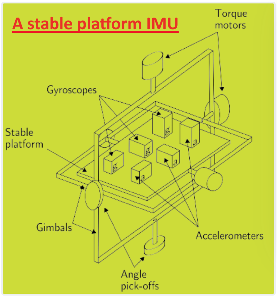
In stable platform systems, the inertial sensors are placed on a platform that is isolated from any external rotation. This means the platform stays aligned with the global frame. To achieve this, the platform is mounted using gimbals, which allow it to move freely in all three axes, as depicted in Figure below. Gyroscopes mounted on the platform detect any rotations of the platform. These signals are then sent to torque motors, which adjust the gimbals to counteract these rotations and keep the platform aligned with the global frame.

To determine the orientation of the device, the angles between adjacent gimbals are measured using angle pick-offs. And to calculate the device’s position, the signals from the accelerometers mounted on the platform are double integrated. It’s important to subtract the acceleration due to gravity from the vertical channel before performing the integration. The algorithm for inertial navigation in stable platform systems is illustrated in Figure below.

2. Strapdown System.
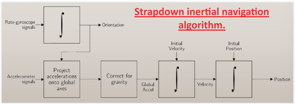
In strapdown systems, the inertial sensors are firmly attached to the device, meaning they measure quantities in the body frame rather than the global frame. To keep track of orientation, the signals from the rate gyroscopes are integrated over time. For tracking position, the signals from the three accelerometers are converted into global coordinates using the device’s known orientation, which is determined by integrating the gyro signals. Then, like in stable platform systems, the global acceleration signals are integrated. This process is illustrated in Figure below.

Both stable platform and strapdown systems rely on the same basic principles. However, strapdown systems have less mechanical complexity and are typically smaller in size compared to stable platform systems. These advantages come at the expense of increased computational complexity. With the decreasing cost of computation, strapdown systems have become the more prevalent type of Inertial Navigation Systems (INS).
What Makes Inertial Navigation Work?
Inertial navigation works by utilizing accelerometers to measure acceleration and gyroscopes to measure changes in direction over time. Here’s how it breaks down:
- Acceleration Measurement: When an object moves, it accelerates. By measuring this acceleration over time using accelerometers, we can track how much the object moves.
- Directional Changes: If we also keep track of the direction in which the object is accelerating, gyroscopes can measure changes in direction over time. This information helps us understand how much the object moves in a particular direction.
- Initial Conditions: Knowing where the object started from and in which direction it was initially pointing provides crucial reference points. By combining this information with the measurements from accelerometers and gyroscopes, we can determine the object’s position, velocity, and orientation as time passes.
Inertial Application Areas.
Inertial navigation finds application across various sectors and grades, catering to diverse needs. Here’s how it’s applied across different grades:
Navigation Grade:
- Spacecraft: Inertial navigation is crucial for maintaining orientation and trajectory in space missions, where GPS may not be available.
- Submarines: Submarines utilize inertial navigation systems for underwater navigation, independent of surface-based signals.
- Military Aircraft: Inertial navigation aids military aircraft in navigation, targeting, and situational awareness, especially in scenarios where GPS signals might be jammed or unavailable.
- Commercial Aircraft: In commercial aviation, inertial navigation serves as a backup to GPS and other navigation systems, ensuring continuous and reliable navigation capabilities.
Tactical Grade:
- Attitude and Heading Reference Systems (AHRS): AHRS systems provide essential information on aircraft orientation, pitch, roll, and heading, serving as artificial horizons for pilots.
- Short-term Tactical Guidance: Inertial sensors assist in short-term guidance tasks, such as missile guidance, drone navigation, and tactical maneuvers.
- Aircraft Autopilot: Autopilot systems in aircraft utilize inertial sensors for flight stabilization, maintaining desired orientations and trajectories.
- Guidance Stabilization: Inertial sensors aid in stabilizing guidance systems for rockets, missiles, and other guided munitions.
- GPS Integration: Inertial sensors complement GPS navigation systems, providing continuous navigation capabilities in GPS-denied environments or during GPS signal disruptions.
Short-term (Commercial Grade):
- Small Unmanned Aerial Systems (UAS): Inertial sensors are used in drones for navigation and stabilization, ensuring precise flight control.
- Camera Stabilization: Inertial sensors stabilize cameras in smartphones, drones, and professional camera equipment, minimizing image blur and ensuring smooth video footage.
- Car Electronic Stability Control: Inertial sensors play a role in electronic stability control systems in vehicles, enhancing safety by detecting and mitigating skidding and loss of control.
- Video Games: Inertial sensors enable motion control in gaming consoles and virtual reality systems, enhancing user interaction and immersion.
- Smartphones: Inertial sensors in smartphones enable features like screen rotation, gesture recognition, and step counting.
- Athletic Shoes: Some athletic shoes incorporate inertial sensors for tracking steps, speed, and distance during workouts or runs.
- Motion Sensors: Inertial sensors are used in various applications, including shipping crates, electronics, and medical devices, for detecting motion, orientation, and vibration.
What About the Ionosphere?
The ionosphere, a layer of the Earth’s upper atmosphere, has significant effects on radio signals, particularly those used for navigation like GPS. Here’s how inertial measurements are utilized with respect to the ionosphere:
Primary Application – Mitigating Ionospheric Effects:
- Inertial measurements are used to mitigate the effects of the ionosphere on navigation systems like GPS.
- The ionosphere can cause delays and distortions in radio signals, impacting the accuracy of position fixes obtained from satellite navigation systems.
- By incorporating inertial measurements into the receiver tracking loop, navigation systems can compensate for ionospheric disturbances, improving accuracy and reliability.
Understanding the Ionosphere:
- Before effectively mitigating ionospheric effects, it’s crucial to understand how the ionosphere behaves and how it affects radio signals.
- Scientists and researchers study the ionosphere’s properties, such as electron density and variability, to develop models and algorithms for better navigation system performance.
Secondary Applications – Earthquake and Tsunami Detection:
- Earthquakes and nuclear detonations can cause disturbances in the ionosphere, leading to changes in radio wave propagation.
- Detection networks are beginning to use inertial measurements along with GNSS (Global Navigation Satellite System) measurements to detect and characterize earthquakes:
- Inertial measurements provide high-frequency content of the quake, complementing the lower frequencies obtained from GNSS measurements.
- Similarly, tsunami prediction networks are starting to use accelerometers, which are a type of inertial sensor, along with GNSS receivers to detect seismic activity and predict tsunamis:
- Accelerometers measure ground motion, providing additional data for early warning systems.
- GNSS receivers track the precise location and timing of seismic events, aiding in tsunami prediction and warning dissemination.
Inertial measurements play a important role in mitigating ionospheric effects on navigation systems, understanding ionospheric behavior, and enhancing earthquake and tsunami detection capabilities when combined with GNSS measurements.
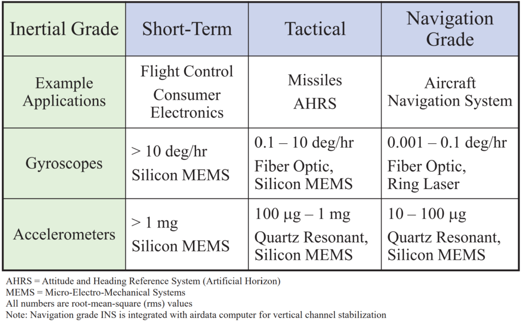
Short-Term, Tactical, Navigation Grade.
The terms “Short-Term,” “Tactical,” and “Navigation Grade” refer to different levels of precision and reliability in inertial navigation systems.

Reducing Drift In Inertial Navigation System
Drift, mainly caused by errors in attitude computation, poses a significant challenge for pure inertial navigation systems. Strategies to prevent drift typically fall into two categories: sensor fusion and domain-specific assumptions.
Sensor fusion involves combining signals from multiple types of sensors to update or maintain the state of a system. In inertial navigation systems, this state usually includes orientation, velocity, and displacement measured in a global frame of reference. Sensor fusion algorithms use signals from IMU accelerometers and gyroscopes along with data from additional sensors. Popular techniques for sensor fusion include Kalman and particle filters, although the specifics of implementing these algorithms are complex.
One common approach to reduce drift is by periodically correcting it using position data from absolute positioning systems like GPS. These systems provide drift-free positions, which are integrated with accelerometer and gyroscope signals to fill in gaps between GPS updates. However, GPS may not be suitable for indoor use or scenarios requiring high accuracy. Magnetometers, which measure magnetic field strength, are another sensor used to reduce drift. While not as accurate as gyroscopes, magnetometer data can be fused with gyroscope data to improve orientation accuracy.
Domain specific assumptions leverage knowledge about the movement of the device to minimize drift. For example, in NavShoe, an IMU mounted on a shoe tracks pedestrian movement. The assumption that a pedestrian’s foot has zero velocity when touching the ground allows for periodic corrections to velocity drift. However, reliance on such assumptions poses risks if they are violated, as in the case of using an escalator.
In summary, mitigating drift in inertial navigation involves a combination of sensor fusion techniques and leveraging domain-specific assumptions, each with its advantages and limitations.
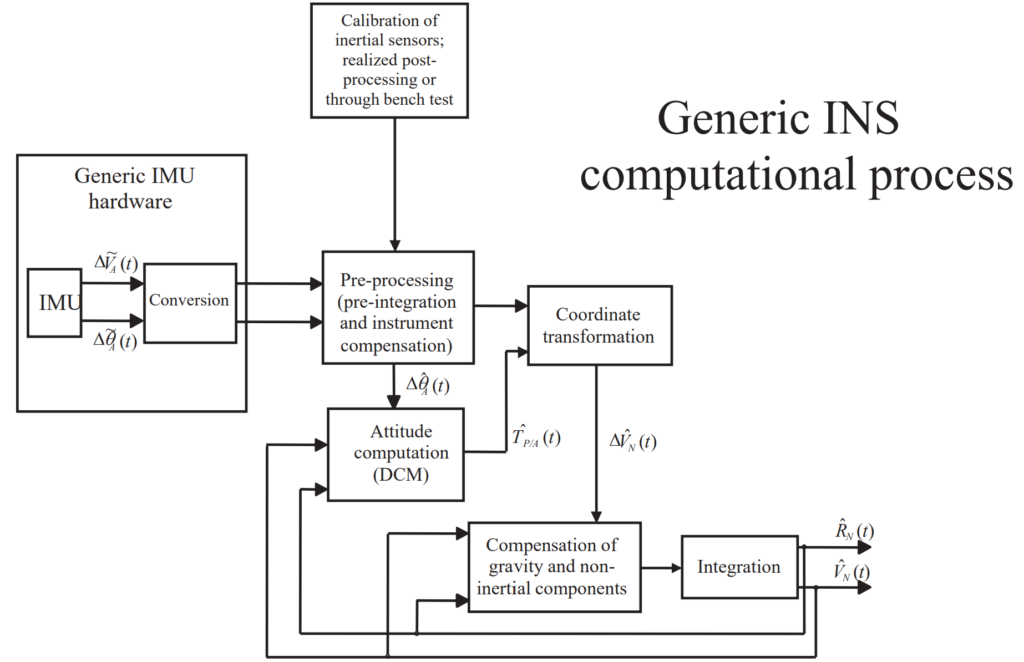
INS Functional Components
An Inertial Navigation System (INS) comprises several key functional components that work together to determine the position, orientation, and velocity of a moving object. These components include:

INS Future Trends.
Future trends in inertial navigation systems (INS) indicate several key advancements and developments:
- Cost Reduction and Performance Enhancement: The cost of inertial sensors is expected to decrease further while their performance continues to improve. This trend opens up opportunities for non-tactical grade applications in sectors such as automotive and consumer electronics.
- Low-Cost Navigation Grade IMUs: Despite advancements, truly low-cost navigation-grade IMUs suitable for a wide range of applications are not expected to be available in the near future due to the complexity and precision required for navigation-grade performance.
- Advanced Calibration Techniques: Performance improvements in INS are likely to be achieved through the implementation of advanced calibration techniques, enhancing the accuracy and reliability of navigation data.
- Integration with GNSS and Other Navigation Sensors: Integration of INS with Global Navigation Satellite Systems (GNSS) and other navigation sensors will continue to evolve. Ultra-tight integration techniques, including carrier phase integration, will improve navigation accuracy, especially in challenging environments.
- Signal Integration and Tracking Loop Design: Innovations in signal integration and tracking loop design will enable longer signal integration times, enhancing the resilience of INS in situations where satellite signals are weak or obstructed.
- Integration with Software-Defined Radios and Batch Processing: INS integration with software-defined radios and batch processing techniques will facilitate open-loop tracking, allowing for more efficient navigation data processing and analysis.
These future trends indicate a promising trajectory for INS technology, with improvements in affordability, performance, and integration capabilities paving the way for widespread adoption across various industries and applications.