Power Transformer Diagnostics – SABP-P-009 Download
Diagnostic of power transformer integrity is a very complex and nonlinear with many uncertainties processes. However, careful interpretation of testing results of a designated unit is vital to correctly discover any imminent failure. Well-planned remedy actions as a consequence of correct diagnostic tools help avoiding plant power transformers and power grid interruptions.
The purpose of this practice is to establish guidelines in interpreting the results out of the Preventive Maintenance (PM) Testing of oil-filled Power Transformers.
Power Transformer Diagnostics References
Industry Codes and Standards
American National Standards Institute
ANSI C57.12.00 – Standard General Requirements for Liquid-Immersed Distribution, Power, and RegulatingTransformers
ANSI C57.12.10 – American National Standard for Transformers 230 kV and below 833/958 through 8333/10,417 kVA, Single-Phase, and 750/862 through 60,000/80,000/100,000 kVA, Three- Phase without load Tap Changing; and 3750/4687 through 60,000/80,000/100,000 kVA with Load Tap Changing – Safety Requirements
IEEE C57.104 – Guide for the Interpretation of Gases Generated in Oil-Immersed Transformers
ANSI/ASTM-D 971 – Standard Test Method for Interfacial Tension of Oil Against Water by the Ring Method
ASTM-D 5837 – Standard Test Method for Furanic Compounds in Electrical Insulating Liquids by High Performance Liquid Chromatography
ASTM-D 3487 – Standard Specification for Mineral Insulating Oil Used in Electrical Apparatus
IEEE 62 Guide for Diagnostic Field Testing of Electric Power Apparatus – Part 1: Oil-filled Power Transformers, Regulators, and Reactors
NFPA 70 B Recommended Practice for Electrical Equipment Maintenance, National Fire Protection Association PEB 5 Transformer Nitrogen Advisory
1. Dissolved Gas Analysis
Dissolved gas analysis consists of sending transformer oil samples to an independent
laboratory for testing. The most important indicators are the individual and total
combustible gas (TCG) generation rates based on IEC 60599 and IEEE C57.104 standards.
This guide uses combinations of individual gases and Total Dissolved Combustible Gas
(TDCG) as indicators. The four IEEE conditions are defined and gas levels are in Table
1 and 2.
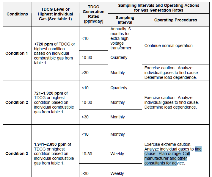
Condition 1: TDCG below this level indicates the transformer is operating satisfactorily. Any individual combustible gas exceeding specified levels in Table 2 should have additional investigation.
Condition 2: TDCG within this range indicates greater than normal combustible gas
level. Any individual combustible gas exceeding specified levels in table 2 should have
additional investigation. A fault may be present. Take DGA samples at least often enough to calculate the amount of gas generation per day for each gas. (See Table 2 for recommended sampling frequency and actions.)
Condition 3: TDCG within this range indicates a high level of decomposition of cellulose insulation and/or oil. Any individual combustible gas exceeding specified levels in table 1 should have additional investigation. A fault or faults are probably present. Take DGA samples at least often enough to calculate the amount of gas generation per day for each gas.
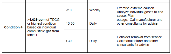
Condition 4: TDCG within this range indicates excessive decomposition of cellulose
insulation and/or oil. Continued operation could result in failure of the transformer.

{Transformers generate some combustible gases from normal operation, and condition
numbers for dissolved gases given in IEEE C-57-104-1991(table 1 above) are extremely
conservative. Transformers can operate safely with individual gases in Condition 4 with
no problems, provided they are stable and gases are not increasing or are increasing very
slowly. If TDCG and individual gases are increasing significantly (more than 30 ppm per
day [ppm/day]), an active fault is in progress. The transformer should be de-energized
when Condition 4 levels are reached.}
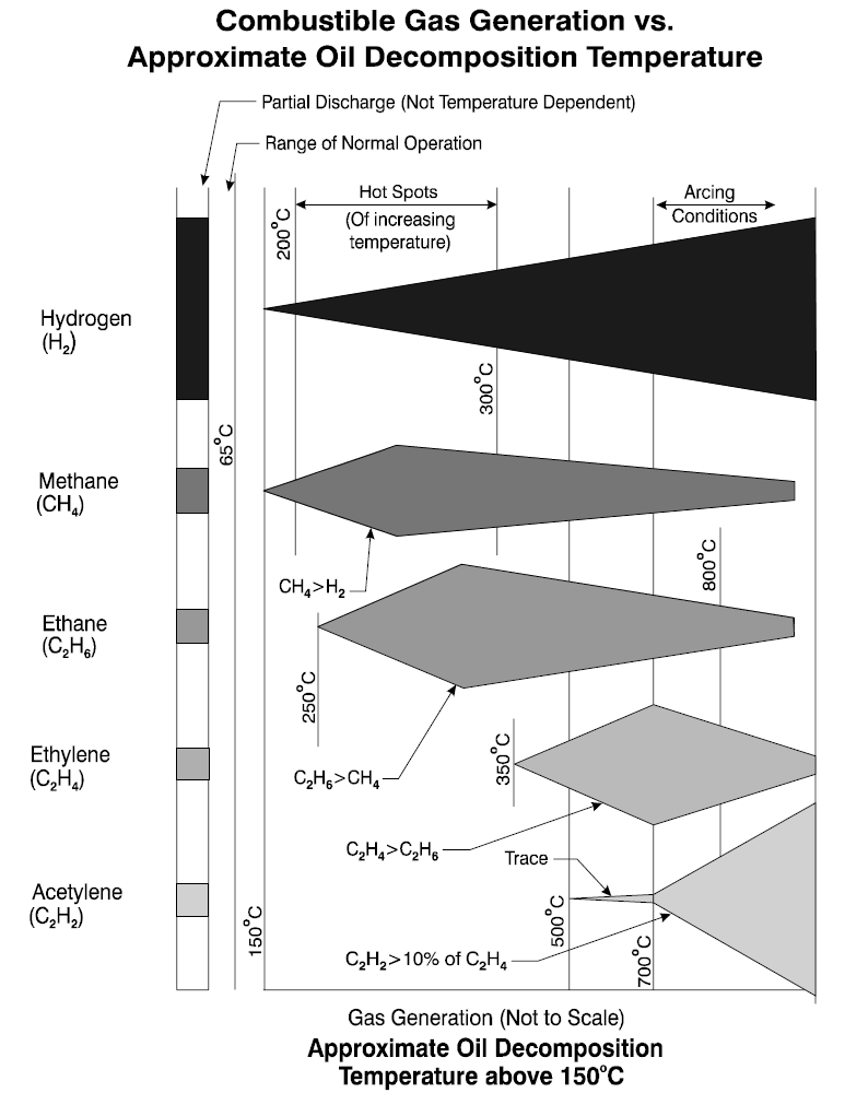
A sudden increase in key gases and the rate of gas production is more important in evaluating a transformer than the accumulated amount of gas. One very important
consideration is acetylene (C2H2). Generation of any amount of this gas above a few ppm indicates high-energy arcing. Trace amounts (a few ppm) can be generated by a very hot thermal fault (500ºC or higher). A one time arc, caused by a nearby lightning strike or a high voltage surge, can also generate a small amount of C2H2. If C2H2 is found in the DGA, oil samples should be taken weekly or even daily to determine if additional C2H2 is being generated. If no additional acetylene is found and the level is below the IEEE Condition 4, the transformer may continue in service. However, if acetylene continues to increase, the transformer has an active high-energy internal arc and should be taken out of service immediately. Further operation is extremely hazardous and may result in explosive catastrophic failure of the tank, spreading flaming oil over a large area.
Table 2 – Actions Based on Total Dissolved Combustible Gas (TDCG)
Commentary Notes:
• DGA analysis shall not be based on one sample; a sample may have been mishandled or
mislabeled either in the field or lab.
• The highest condition based on individual combustible gas or TDCG can determine the
condition (1,2,3, or 4) of the transformer. For example, if the TDCG is between 1,941 ppm
and 2,630 ppm, this indicates Condition 3. However, if hydrogen is greater than 1,800 ppm,
the transformer is in Condition 4, as shown in table 2.
• When the table says “determine load dependence,” this means try to find out if the gas
generation rate in ppm/day goes up and down with the load. The transformer may be
overloaded or have a cooling problem. Take oil samples every time the load changes; if
load changes are too frequent, this may not be possible.
• To get the TDCG generation rate, divide the change in TDCG by the number of days
between samples that the transformer has been loaded. Down-days should not be
included. The individual gas generation rate in ppm/day is determined by the same
method.
Table 2 assumes that no previous DGA tests have been made on the transformer or that
no recent history exists. If a previous DGA exists, it should be reviewed to determine if
the situation is stable (gases are not increasing significantly) or unstable (gases are increasing significantly).
Figure 1 illustrates temperature relationships, gas types, and quantities. These relationships represent what generally has been proven in controlled laboratory conditions.
Figure 1: Combustible Gas Generation Versus Temperature