WHAT IS CONTROL VALVE HANDBOOK DOWNLOAD

This article is about WHAT IS CONTROL VALVE HANDBOOK DOWNLOAD and focusing to the engineers, technicians and supervisors. You will find lot of documents related to this article. Just navigate our website  www.paktechpoint.com  and find more articles. Please! Do not forget to subscribe our You tube channel also. Thanks in Advance.

PLEASE SUBSCRIBE OUR PAKTECHPOINT YOUTUBE CHANNEL


Wait some time if Book is not loaded…………….!


Emerson-Control-Valve-HandBook

WHAT IS CONTROL VALVE HANDBOOK DOWNLOAD

This book is offering details as mentioned following chapter wise.

In First Chapter of this book offers Introduction to Control Valves

In 2nd Chapter of this book includes information Control Valve Performance

In 3rd Chapter of this book covers Valve and Actuator Types

In 4th Chapter of this book is comprehensive guide to Control Valve Accessories

In 5th Chapter of this book describes Control Valve Selection

In 6th Chapter of this book develops Special Control Valves

In 7th chapter of this is discussing about Steam Conditioning Valves

In 8th chapter of this book gives information about Installation and Maintenance

In 9th chapter of this book illustrates about Standards and Approvals

In 10th chapter of this book explains about Engineering Data about control valve.

WHAT IS CONTROL VALVE HANDBOOK DOWNLOAD

Read more

VALVES EXPLANATION AND ITS TYPES

VALVES EXPLANATION AND ITS TYPES

Liquids or gases flow from areas of higher pressure to areas of lower pressure. If a pipe is connected to a tank of water, the water flows out of the pipe opening because the pressure in the tank is greater than the pressure outside.

valve basic

For a liquid or gas to flow, there must be a pressure difference, or drop.

valve basic

Suppose the opening of the pipe is partially closed with a piece of sheet metal, the amount of flow changes, and if the pipe is completely closed, the flow stops. Changing the amount of opening of the pipe changes the flow.In industrial piping, control of flow is of high importance. Mechanical devices that are used in such piping for flow control are called valves.

valve basic

Basically, a valve stops flow through a pipe by closing the opening of the pipe. A valve that is partially open allows partial flow to exist, and is said to be in a throttling position.

Any valve can be in one of three positions: throttling, fully open, or fully closed.

GATE VALVES

If two pipes are joined closely together, flow can exist through them.

GATE VALVE

If a piece of sheet metal is inserted between the joints, flow stops.

GATE VALVES

The drawing below shows two gate valves installed between two pipes.

GATE VALVE

A liquid is flowing through valve A. A gate valve stops flow by placing a metal gate across the opening. When the valve is completely open, the gate is raised out of the line of flow. In the open position, the gate causes practically no resistance to flow. When flow encounters resistance, or changes direction, turbulence and pressure drop occur.

When a gate valve stops the flow, the gate resists the pressure. Therefore the gate has to be strong enough to resist the pressure.

GATE VALVE

The pipes are always attached to the body of the valve.

The valve has a body with flanged ends with boltholes in them. The end of the pipe is also flanged and the pipe and valve are held together by bolts. To have a tight, leak proof connection, a gasket is inserted between pipe and valve.

The part of the valve that is mounted on top of the body to form a tight enclosure is called the bonnet. In the valve below, the bonnet and body are also bolted together.

Between the bonnet and body, a bonnet gasket is inserted for tight closure.


Read more

CALIBRATION OF VALVES WITH ACTUATOR AND ACCESSORIES

CALIBRATION OF VALVES WITH ACTUATOR AND ACCESSORIES

Note:Valve calibration will be carried out at warehouse up to 2” (inch) without transportation and the 3” (inch) above are carried Site calibration.
·         TSO Valves shall be calibrated after the seat leakage test. Hand wheel test as the part of calibration, manual operation of the hand wheel shall override the automatic operation.

Self-Actuating Valves (i.e., pressure regulator)

Visual checking shall be carried out to ensure that there is no damage on the body.
Tag no., range, & type shall conform to the data sheet.
If required, detailed calibration procedure for self-actuating valves shall adhere to manufacturer’s manual and shall be confirmed.
Final set point adjustment is required during start-up operation in order to make it suitable with process variables.
Note: No such confirmation (final set point) is required for pressure regulator with internal relief  feature (i.e., air filter regulator for CV, I/P, etc.).

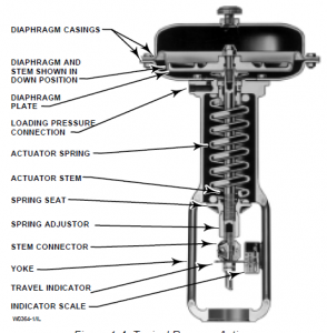
Diaphragm Actuator, Spring Adjustment (Bench Set)

The following items shall be checked:
·                  Size and type
·                  Stroke range
·                  Spring range
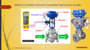
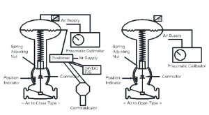
Hook up testing equipment as illustrated below:

Procedure for Valve calibration With Pneumatic Calibrator:

1. Adjust pneumatic signal so that the valve closes slowly, and stop when the valve fully closed.
2.  Dynamic error band, which is the difference between upscale and downscale plots at any given input signal, shall be less than 3.0% which valve travel. If the desired value cannot be obtained with spring
adjustment, change stem length by adjusting connector assembly.
3.  Adjust pneumatic signal so that the valve opens slowly, and stop when the valve fully opened.
4.  Read the pneumatic signal value and compare it with the actuator’s range. If the difference is greater than 3.0%, change spring and recheck closing and opening.
5.  Adjust position indicator scale so that the indication works correctly.
6.   Inject pneumatic signal 0%, 25%, 50%, 75% and 100% of its range and read valve position with signal rising and falling.
7.  Check air failure action by disconnecting air supply.
8.  Check power failure action by disconnecting power supply.
9.  Speed of stroking time from full open to full close shall be checked, if required. Note down in form and compare with datasheet.
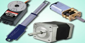
Other Type Actuator
The actuators other than diaphragm type shall be checked for the following items before the stroke check
(positioner calibration).
Piston Type Actuator
·                   Size and type
·                   Stoke range
·                   Leakage
 Electrical Actuator
·                   Electrical insulation of motor and other electrical parts
·                   Limit switches and/or torque switches
·                   Positioner assembly
·                   Power requirement
·                   Local open/close/stop switch
·                   Hand wheel operation

Positioner (Stroke check) Procedure Calibration:

                    I. After checking the valve stroke all valves shall be checked with positioner, positioner shall be
checked.                 Functions of HART Calibrator please click here.
                  II.  Determine signal range and characteristics curve through full stroke of valve. Before calibration curve shall be provided.Select proper travel character cam if provided.
                 III.   Connect Power Supply and and/or air supply to the positioner and actuator.
                 IV.      Connect proper input signal source (4-20mA) to the positioner.
                 V.         Adjust input signal so that the valve closes slowly, and stop when the valve is fully closed.
                VI.       Read the input signal and adjust zero adjustment when error is found. Repeat steps until the valve corresponds with closing signal within error limit.
               VII.       Adjust input signal so that the valve opens slowly, and stop when the valve fully opened.
              VIII.       Read the input signal and adjust zero adjustment when error found. Repeat step until the valve corresponds with closing and opening signal within error limit.
              IX.       Inject signal 0%, 25%, 50%, 75%, and 100% of its range and read valve position with signal rising and falling. Action of the positioner shall be checked (direct or reverse).
               X.       Analyse the stroke characteristic curve and figure out the reproducibility which includes dead band and hysteresis.
              XI.       If the character or the reproducibility is not acceptable, check feedback cam style and/or mechanical condition of all moving parts and correct existing deficiencies.
              XII.       Mechanical stops shall be checked as per data sheet.

Read more

error: Content is Protected.