In this article we are going to be discussed transformer oil, transformer oil testing, oil used in transformer, bdv of transformer oil.
TRANSFORMER OIL FILLING PROCEDURE
Flushing and vacuum of transformer tank shall be performed as per manufacturer’s recommendations.
Heating and filtering of insulating transformer oil and filling shall be performed as per manufacturer’s recommendations.
Remove a sample of insulating transformer oil in accordance with ASTM D-923. Sample shall be tested for the following:
a) Dielectric breakdown voltage.
b) Acid neutralization number.
c) Specific gravity.
d) lnterfacial tension.
e) Color
f) Visual condition.
g) Water in insulation liquid.
h) Dissipation factor or power factor. ANSI/ IEEE C57.106
Remove a sample of insulating transformer oil in accordance with ASTM D-3613 and test shall be performed for dissolved gas analysis (DGA). ANSI/ IEEE C57.104 or ASTM D3612, NETA, ATS-Sec.7.2.2.2.11 Temperature devices shall be installed and verify setting and operation.
Cooling fans and pumps shall operate correctly and that fan and pump motors have correct over current protection, if applicable. NETA, ATSSec.7.2.2.1.11 .
Correct liquid level shall be verified in all tanks and bushings. NETA, ATS-Sec.7.2.2.1.13.
Operation of all alarm, control, and trip circuits shall be verified from temperature and level indicators, pressure relief device, and fault pressure relay, if applicable. NET A, ATS-Sec. 7 .2.2.1.10 .
Transformer tank shall meet the Standard requirement of SAES-P-111, Sec. 9.
Insulation resistance test shall be performed before and after installation of surge arresters.
Main tests are Transformer testing, transformer oil testing, transformer winding, current transformer, Transformer Ratio test.
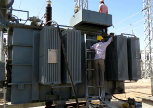
TRANSFORMER TESTING ON SITE
After a transformer has been completely assembled on site, it must be tested to confirm successful shipment and correct assembly. All tests must be carried out with instruments that have traceable, valid calibration. These instructions are intended to provide guidelines in the test of transformers to maintain their quality and reliability.
They are intended for the guidance of personnel who have been trained for, or who have experience in test of high-voltage electrical power equipment, including the use of good safety practices. These instructions are intended to supplement, and not eliminate the necessity for such training.
The Transformer testing results are to be recorded on a Test Record. The second sheet of this Transformer testing Record is a list of all possible tests, some of which may not be applicable. When the on-site project manager or the assembly supervision has marked all applicable tests, this sheet forms an order-bound directive for the tests to be carried out.
Main tests are Transformer testing, transformer oil testing, transformer winding, current transformer,Transformer Ratio test.
Transformer Ratio test
The Transformer Ratio test is used to confirm that the winding turns ratio is consistent with the voltage ratio as shown on the Nameplate.
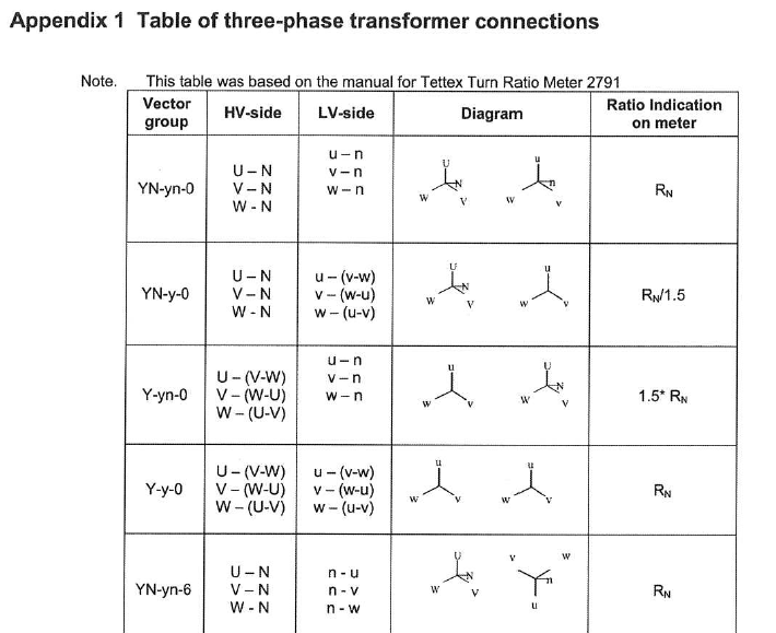
Transformer Ratio test This is done primarily to check for shipping damage and to confirm that any tap-changer leads installed in the field have been correctly connected. In addition to the ratio measurement, exciting current is also often measured. The ratio measurements is normally done with a ratio bridge. Table of three-phase transformer connections Appendix 1. Transformer Ratio test
Transformer Winding resistance test
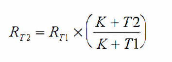
Measure the resistance of each winding at the rated and extreme tap positions and compare the results to the original value in the Factory test report. If the Tap Changer connections have been made at site, measuring at all positions should be done. Transformer winding Resistance is dependent on the temperature of the winding. The mean temperature of the oil is representative of the winding temperature, and providing that the oil is at a uniform temperature, the top oil temperature gauge value can be used. Resistance comparison must always be made at a common temperature. The conversion formula for copper and aluminium transformer winding is show below. The formula giving the relation between the resistance and the temperature is:
where RT2 = Resistance of the winding at temperature T2 RT1 = Resistance of the winding at temperature T1 K = 234.5 for winding made of copper ace to IEEE, K = 235 for winding made of copper ace IEC K = 225.0 for winding made of aluminium The time constant may be very long when low voltage and low current sources are used.
Note:
A high voltage surge occurs at interruption of DC current at end of measurements. A discharge circuit should be used. Eg. see IEEE Std 62 figure 2.
Main tests are Transformer testing, transformer oil testing, transformer winding, current transformer, Transformer Ratio test.
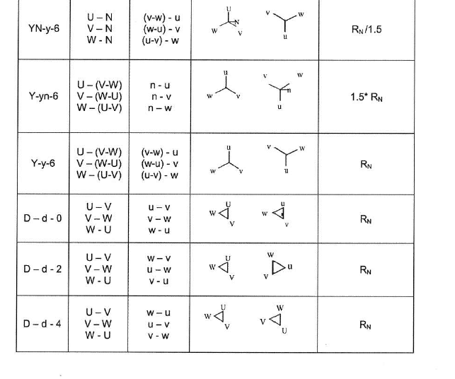
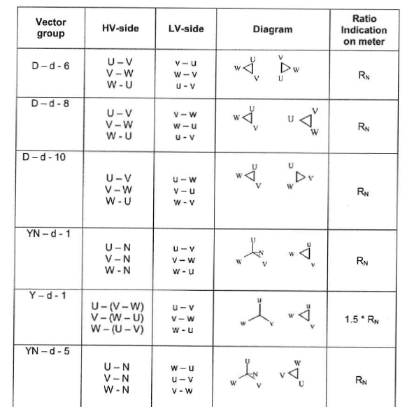
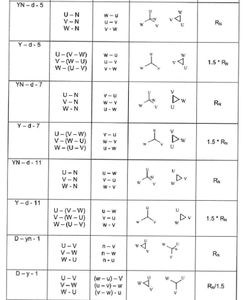
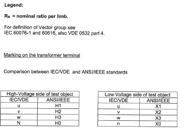
Transformer Check of vector group
The purpose of this series of tests is to check the polarity and the phase relationship of the multiple windings in a transformer. The test is carried out simultaneously with the transformer turns ratio test when using a turns ratio test set. In order to define the connection of a three-phase transformer and to facilitate the parallel connection with other transformers, the international standards prescribe specific vector groups. Every country has its own designation for the vector groups. IEC and IEEE (in USA) have recommended a method that will result in standardized and fully defined designations.
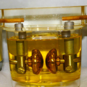
Transformer Insulation resistance test
Insulation resistance can give some information of the integrity of the insulation structure. As an insulation structure begins to deteriorate due to contamination and moisture, the insulation resistance will decrease. The test equipment used is a DC insulation tester (Megger). It is essential that it is of a type, which is suitable for measurement on transformers and transformer core insulation. Ensure that bushings are clean and dry. Insulation resistance is temperature dependence why it is important that the oil temperature is noted. After the test has been completed, all terminals shall be grounded time enough to allow any trapped charge to decay to negligible value.
Transformer main windings
When conducting an insulation resistance test on transformer windings, a 2.5 or a 5 kV megger can be used. Test every winding to ground and between each winding. Make sure that the bushing porcelains are cleaned since dirt deteriorates the insulation resistance. The transformer tank must be grounded during the test. If the insulation resistance is 1 Mn/kV system voltage for the winding, it is acceptable. If lower values are measured, this must be reported to an ABB representative. According to IEEE the following shall be measured. High voltage to low voltage and ground, low voltage to high voltage and ground.
This article is about racks and console cabinets installation in process interface buildings.
Process interface building Installation Activities
Electronic Control System required Installation and Visual Inspection for DCS/ESD 1/0 & CPU Racks and Operator Consoles. Check the actual location and foundation dimensions against the Vendor’s equipment drawings of the equipment’s to be installed.
Ensure that the transport of these equipment’s from the laydown yard to the Process Interface Building should be thoroughly Rigging of big equipment’s such as IRP, DCS, ESD 1/0 and CPU Racks should conform to the manufacturer recommendations.
From the trailer/ truck using a suitable crane lift down the panels to the cleared staging
The panels shall be un-crated in the presence of Contractor and Company Representatives inside the
The receiving inspections shall be done in the PIS before i
From there using pallet truck assisted by Technician / craftsman each panel shall be moved slowly one-by-one to its temporary location inside the PIS.
Layout the actual equipment dimension measurement on the location where the equipment is to be installed.
Marked the possible location of equipment’s / panels / racks base support. The location of the equipment should be as approved in I FC
In Process Interface Buildings, 3 types of installation will generally be provided is on the base plate, on the raise floor without base plate and the other is on wall mounting.
All supports, base plates, floor fixings, penetrations and cable entries shall be checked for its location, alignment, level and overall measurement as against the actual dimension of the equipment’
Provide adequate protection to finish floors, walls, and other equipment to prevent accidental damage during the
Install the equipment’s/ panels/ racks to its respective location by using pallet truck or tube Always exercise maximum safety in transporting the panels. Pallet truck shall have a greater capacity than Control equipment to be lifted.
Mount and anchor the equipment/ panels / racks in accordance with the Vendor manuals and IFC
The complete assembly shall be checked to ensure the alignment and level after bolt tightening.
Bond the equipment’s/ panels/ racks to its dedicated safety grounding bus-bar as described in SAES-P-111.
Vacuum cleaned inside panels / racks to removed dust and any foreign objects.
Repair/ touch up paint any damage, scratches on the equipment’s/ panels and racks shall be carried out only by written instruction from system Vendor.
This method statement covers the grouting application for equipment foundations, precast concrete and structural foundations including all operations necessary for the surface, formworks, proper mixing, placing, finishing and curing for non-shrink cementitious grouting.
Grouting application shall be in accordance with Standard Drawing for Grout and Surface Preparation unless otherwise specified in issued for construction drawings.
TOOLS AND EQUIPMENT FOR GROUTING WORKS
Tools and equipment should be in good condition and must be checked by Safety Officer / Mechanical Supervisor prior to use in the construction area. These included but not limited to the following:
Resin mixer drill and/or Spiral Paint Mixer
Bagger mixer (depends on quantity required)
Grout mixers with container suitable for quantity required
Drill mixer
Mixing paddle
Pan mixers or rectangular container
Pushing tools (use to assist the grout to fill for far location)
Caulking guns
Finishing trowel
Wheel-borrow, bucket
Survey instrument
Starret level
Air compressor
Formworks with releasing oil
Vacuum cleaner
Power stiff bristle brushes
Hand tools
Electric/Manual saw
General Requirements
Grouting materials shall be in accordance with the project specification Section 3.5 for Epoxy grout and Section 4.5 for cementitious grout. Only approved COMPANY grout products shall be used.
All materials shall be delivered to job site in original unopened packages and shall be stored in accordance with the manufacturer’s recommendation.
Grouting materials shall be stored out of direct sunlight, clear of the ground on pallets protected from rainfall. Avoid excessive compaction.
The grout shall be stored, mixed, placed at temperatures recommended by manufacturer.
Preparatory Works
Confirm that structural and equipment foundations released for grouting has reached the required strength or has cured the length of time as per project specification. For precast concrete column and foundation; precast column shall be aligned and accepted. Prior to grouting; the base plate level must be approved by COMPANY.
Secure valid Work Transfer Sheet from civil/structural and mechanical group signed by respective department confirming that the equipment and/or structure is ready for grouting.
Secure a valid work permit before starting any grouting works.
Prepare grout area in accordance with the extent of grouting as shown in Grouting Method “Standard Drawing for Grout and Surface Preparation”
Contact surfaces of grout shall be chipped/rough to remove all laitance and weak surface materials. A sound and clean substrate shall reveal.
Concrete chipping and removal must not be performed with heavy tools such as jackhammers as they could damage the structural integrity of the foundation. A chipping hammer with a chisel bit is the preferred tool for this purpose.
When surface preparation is completed, remove all debris from bolt pockets by vacuuming. For foundation’s top surface area, use power wire brushing to remove loose contaminants followed by blowing of oil free air using air compressor. All surfaces should be thoroughly cleaned to ensure a strong bond develops between interfaces.
The underside of base frame equipment shall be clean, dry and unpainted to allow grout to bond.
A minimum of 25mm of concrete must be removed for damaged concrete down to exposed fractured coarse aggregate.
Bolts and sleeves shall be with seal and dry.
Ensure the base frame or skid is properly positioned and leveled.
Formworks shall be built of materials of sufficient strength and securely anchored and sealed to withstand the liquid head and forces developed by grout during placement. With sealant to avoid grout loss and dimension to permit grout placement.
Grout forms shall have chamfer strips at all vertical corners and at the horizontal surface of grout.
Bond breaker compatible with manufacturer recommendations shall be applied to surfaces of formworks and temporary fixing pieces to facilitate removal after the grout has hardened.
Confirm that proper number and size of air relief holes in base plates were provided to prevent voids.
Cover grouting work area on floor with plastic to protect the floor.
IEC 60502 Extruded Sold Dielectric Insulated Power Cables for Voltages from 1KV to 30KV
IEC 60540 Test Methods for the Insulation & Sheaths of Electrical Cables & Cord (Elastometric & Thermoplastic Compounds)
IEC 60754 Tests on Gas Evolved During Combustion of Electric Cables
IEC 60811 Common Tests Methods for Insulating & Sheathing Materials of Electric Cables
IEC 60851 Methods of Test for Winding Wires
IEC 61034 Measurement of Smoke Density of Electric Cables Burning Under Defined Conditions, Test Procedures & Requirement
IEC 61158-2 H1 Field bus cables
PROCEDURE POWER CABLE INSTALLATION
Cable installation shall comply with reference codes and design documents.
All cable drum shall be checked with packing list and confirmed no mechanical damage.
During cable drum shifting; check mechanical damage, nameplate with cable schedule & drum list and phase rotation of the cable.
Assure necessary PPE, tools and equipment for cable pulling. Check the latest cable drum list and cable schedule. Prior for cable pulling, QA/QC inspector shall check if all the cable supports are installed and fixed.
All wire and cable shall be megohm meter tested after it is pulled, but prior to termination.
High voltage cable shall be given a hi-pot test after it is pulled and stress relief is installed, but prior to termination.
Electrical cables shall be oil & sunlight resistance and flame retardant shall be used as per IEC 60332.
Cables used for buried or external installation shall be steel wired armoured. Noted that armouring cables are not required within the building, e.g. from control room to control building rack room
Cables shall be installed direct buried on the ground or in formed concrete trenches with backfill, fastened to cable ladder rack or tray and in underground ducts.
Make check for the following during wire and cable installation;
The proper type, size, colour and number of wires & cables are being installed.
For long pulls, the pull is performed as per required pulling tension.
Cable is not pulled around too many bends.
Ambient temperature is above the minimum allowed for the cable insulation.
Proper pulling compound is being used.
For long pulls, allowable pulling tensions are not exceeded.
Cables are not bent on too tight a radius.
Wire and cable is protected and kept clean throughout the pulling operation.