CONTROL SYSTEM INSTRUMENT EQUIPMENT INSTALLATION

CONTROL SYSTEM INSTRUMENT EQUIPMENT INSTALLATION

CONTROL SYSTEM INSTRUMENT EQUIPMENT INSTALLATION

Industry Codes and Standards

NEMA ICS                           Enclosures for Industrial Controls and System

IEEE 1100                            Powering and Grounding Sensitive Electronic Equipment

NFPA 70                               National Electrical Code

Definition of Terms

  • DCS – Distributed Control System
  • ESD – Emergency Shutdown System
  • I/O – Input/Output
  • CPU – Central Processor Unit
  • FAT – Factory Acceptance Test
  • FF – Foundation Fieldbus
  • MCT – Multi Cable Transit
  • PIB – Process Interface Building
  • NEMA – National Electrical Manufacturers Association
  • P&ID – Piping and Instrumentation Diagram
  • PLC – Programmable Logic Controller
  • UPS – Uninterruptible Power Supply
  • NEC – National Electric Code
  • MCC – Motor Control Centre
  • CCR – Central Control Room
  • FAS – Fire Alarm System
  • HART – Highway Addressable Remote Transducer
  • SID – Instrument Segment Diagram
  • ILD – Instrument Loop Diagram
  • SIS – Safety Instrumented System
  • SAT – Site Acceptance Test
  • RTD – Resistenace Temperature Detector

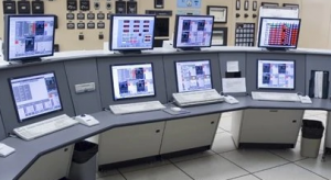
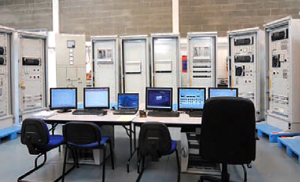
PANEL, RACK & DCS CABINET INSTALLATION

  1. DCS control networks shall be based on IEEE 802.3 CSMA/CD (Ethernet) standard. As per 23-SAMSS-10 Sec. 11.1 para. 11.1.1.
  2. Ensure that the transport of this equipment’s from the laydown yard to the Process Interface Building should be thoroughly planned. Rigging    of big equipment’s such as IRP, DCS, ESD I/O and CPU Cabinets    should conform to the manufacturer recommendations.
  3. Panel, rack and cabinet arrangement shall be checked against the relevant Plan Layout and General Arrangement Drawings and the    latest issued and approved for construction drawing
  4. Where supports are required, these shall be installed in accordance with approved detailed construction drawings.
  5. All support assemblies installed in the control room to support panels, cabinets, consoles, tray, etc. shall be constructed prior to panel
  6. Install panels, racks and cabinets based on approved installation drawings, taking consideration all possible obstacles and clearances    requirements per project specification.
  7. Installation of equipments shall be properly plumbed, aligned and fixing bolt tightened. Where equipment consists of a number of panel    sections, the assembly shall commence from the center section.    Sections on either side of the center shall be alternated, leveled and    shimmed as necessary.
  8. Cabinets, consoles and control panels may be installed on raised floor or bolted to dedicated supports as per approved drawing.
  9. The installation of cabinets shall be carried out in accordance with the control room layout and detailed instructions of the manufacturer. It    shall be approved by EPC/COMPANY and conforms to the latest issued approved for construction drawing.
  10. Where multiple section desks or cabinets are used, care shall be taken to ensure that all wiring (disconnected for shipping purposes) are connected and re-clamped to its pre-shipped condition.
  11. All cabinets shall have a nameplate permanently attached.
  12. Marshalling cabinets shall comply with the requirements of 34- SAMSS-820(Saudi Aramco standard), “Instrument Control Cabinets – Indoors.”
  13. System Cabinets: Saudi Aramco 34-SAMSS-820 requirements shall be applied for all wiring, cables, terminal blocks and ways ducts located within DCS system cabinets which are associated with the    following:
      1. Power supply and distribution
      2. Utility power, lighting, and convenience outlets
      3. Intermediate terminal strips for I/O wiring
      4. Grounding

PANEL, RACK & DCS CABINET INSTALLATION

Read more

HEAT TRACING INSTALLATION AND TESTING

HEAT TRACING INSTALLATION AND TESTING

HEAT TRACING INSTALLATION AND TESTING

Preparatory Works for Heat Trace Installation

  1. Ensure that work permit is prepared and secured. Safety concern and precautions are being complied and discuss with the crew.
  2. Subcontractor shall appoint qualified employees as their ‘competent persons’. Such persons shall be capable of working safely and shall be knowledgeable on the precautionary techniques, personnel protective equipment for the installation of heat tracing.
  3. Equipment, tools and other logistics shall be prepared and are ready for installation of heat tracing.
  4. Material Handling prior to installation of heat tracing.
  5. Identify the heating cable to ensure proper type and quantity is received.
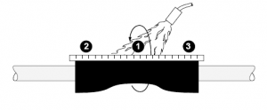
  6. Cable model number shall be visible on the parallel heating cables (on braided cables, information is printed on the jacket below the braid).
  7. Visually Inspected material for damage incurred during shipment.

Work flow documents for heat tracing hand-over

  • Piping QC will handover released package to Electrical Team.
  • Mechanical QC will handover released package to Electrical Team.
  • After completion of electrical work Electrical QC will handover released package to Insulation.
  • After completion of electrical work Electrical QC will handover released package to Insulation.
  • Document handover with duly accomplished Work Transfer

Preparatory Works for Heat Trace Testing

  1. Review appropriate supplier literature, design drawings and specifications before starting the job.
  2. Compare heater cable, connection and end seal kits and all associated tracing components manufacturers and model number against drawing and specification.
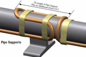
  3. Visually inspect heater cable for damage, correct installation at pipe shoes and other heat sinks.
  4. Correct installation tape spacing, heater orientation on pipe and overall general construction installation.
  5. Check the design heater length against the actual length (start and stop cable lengths may be printed on the heater).
  6. Inspect end seals for proper sealing and installation.
  7. Inspect connection kit for proper location sealing and installation.
  8. Inspect RTD for correct type, securely taped to pipe at the right location, damage (such as field bending) and correct wiring.
  9. Verify continuity of heater cable. This to be documented at receipt of material on reel, after the heater cable is installed and after insulation is installed.
  10. Measure insulation resistance of each heater cable conductor. This is to be documented at receipt of material on reel, after the heater cable is installed and after insulation is installed.


Read more

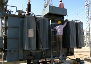
POWER TRANSFORMER INSTALLATION PROCEDURE

POWER TRANSFORMER INSTALLATION

POWER TRANSFORMER INSTALLATION PROCEDURE

Industry Codes and Standards for Transformer

ANSI/NFPA      70                

American National Standard Institute/National Electrical Code

ANSI/IEEE C57.106-2015             

Guide for Acceptance and Maintenance of Insulating Mineral Oil in Electrical Equipment

ANSI/NETA ATS-2009                  

Standard for Acceptance Testing Specification for Electrical Power Equipment and Systems

TOOLS AND EQUIPMENT FOR TRANSFORMER INSTALLATION

Tools and equipment needed should be in good condition and must be checked by Supervisor / Safety Engineer prior to use in the construction area.  These includes but not limited to:

  • Boom Truck
  • Electrical Hand Tools
  • Mobile Crane
  • Hydraulic Pallet Jack
  • Spirit Level
  • Torque Wrench
  • Common Hand Tools
  • Measuring tape
  • Insulation Resistance Test Set
  • Transformer Turn Ratio (TTR) Test Set
  • Secondary Current Injection Unit
  • Transformer Winding Resistance Test
  • Current Transformer Test Set
  • Power Factor/ Dissipation Test Set
  • Digital multi-meter, Clamp on Ammeter, Thermometer
  • 3ph, AC power Supply

All tools utilized in a classified area should be intrinsically safe and suitable for hazardous areas.

GENERAL PREPARATORY WORKS

  1. All permanent materials (including pre-fabricated supports), consumables, equipment to be installed and its accessories, construction area and resources shall be prepared and checked prior to installation works.
  2. Ensure that working areas are safe and ready for installation in coordination with other discipline for the use of the area.
  3. Work Transfer Sheet shall be duly signed and processed by other subcontractors or discipline for the preceding works to avoid confusion and discrepancies in the work responsibilities.
  4. Subcontractor shall appoint qualified employees to perform the activities in a safe manner. Such persons shall be capable of working safely and shall be knowledgeable on the precautionary techniques, personnel protective equipment, shielding and insulating materials and tools.
  5. A competent person will be designated by the sub-contractor who has the capability to identify the existing and predictable hazards in the surrounding or working conditions which are unsanitary, hazardous, or dangerous to personnel, and who has authorization to take prompt corrective measures to eliminate them.
  6. Study erection procedures of heavy power transformer prior to installation.
  7. Special tools shall bear a valid calibration certificates traceable to a national standard indicating calibration validity and periodically (at least six months) checked by a third party laboratory testing facility.
  8. Electrical materials shall conform to all applicable requirements, standard, and specifications prior to release to be used as part of the work.
  9. Review all references such as the latest approved for construction
    (IFC) drawings, layout, and Technical Scope of Work.
  10. All equipment related to power transformer installation works shall be checked after confirming the availability at company warehouse. Visual Inspection shall be conducted for possible factory or handling damage and recorded in appropriate QC Material Receiving Inspection Report form.

Read more

Uninterruptible Power Supply UPS Installation and Testing

UNINTERRUPTIBLE POWER SUPPLY UPS INSTALLATION AND TESTING

Installing an Uninterruptible Power Supply (UPS) is a critical step in safeguarding your electronic equipment against power disruptions. After installing your Uninterruptible Power Supply (UPS), it’s crucial to conduct thorough testing to verify its functionality and readiness to support your critical devices during power outages.

UNINTERRUPTIBLE POWER SUPPLY UPS INSTALLATION AND TESTING

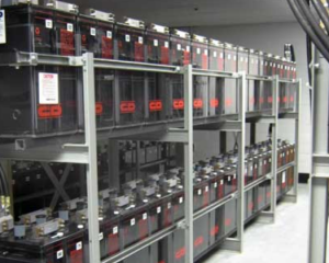
Following are summarized points for Uninterruptible Power Supply (UPS), Battery and Charger Installation.

  1. Equipment, racks panels and its components shall be carefully installed considering all requirements.
  2. Install Uninterruptible Power Supply (UPS) as per vendor’s procedure and data provided for the specific equipment.
  3. A work space of 1 meter shall be allowed in the front of the UPS cabinets. If rear access is required for UPS maintenance, a clearance of 1 m shall be allowed as needed.
  4. UPS System shall be located in a temperature controlled room in which the temperature is maintained at <= 25°C. Redundant AC systems are preferred at the time for continuous and reliable operation.
  5. Cables for the primary AC input, output and the alternate AC source shall be run separate raceways.
  6. Assemble battery racks, batteries, and battery switch as per equipment vendor’s procedure and data provided for the specific equipment.
  7. Position the battery cells on the assembled rack and mount in accordance with vendor’s recommended instruction. Exercise care not to damage cells during lifting operations. Battery cells shall be lifted by the bottom not by the terminals. Ensure that polarity are properly oriented and connected as intended.
  8. Install the bottom plate racks for the substation floor opening as per design engineering company latest Issued for Construction (IFC) Drawings.
  9. Glanding plate boring for cable entry shall be in accordance to the cable sizes.
  10. Install and arrange cable through conduit from battery bank to battery switch and from switch to battery cabinet.
  11. Functional test shall be conducted.
  12. Cable glanding and dressing shall be executed properly and proper terminal lugs shall be installed as per latest Issued for Construction (IFC) Drawings.
  13. Connect all cabling and termination to the system as per Latest Single Line Diagram and latest Issued for Construction (IFC) Drawings. Tighten all the bolted connection using appropriate tools and marked with visual indicator.
  14. Connect all grounding connections to grounding system as per  latest Issued for Construction (IFC) drawings.
  15. Final interconnection shall be checked to ensure tightness and polarity. Check alignment and plumbness of the equipment together with its structure.
  16. Completed installation of UPS and battery shall be preliminary inspected and panels shall be opened for cleanliness to ensure no foreign bodies are present. Dust and dirt shall be removed by using appropriate vacuum cleaner or rags prior to filling of electrolytes to the battery cells as per equipment vendor’s procedure and data provided for the equipment. Battery cells shall be filled-up to the correct line specified by the equipment vendor. Make sure that the cells are clean and free from leakage.
  17. Identifications, nameplates and warning signs shall be properly installed accordingly as per engineering design company latest Issued for Construction (IFC) Drawings.
  18. Any changes shall be incorporated in the “As-Built” drawings.

Read more

LIGHTNING PROTECTION SYSTEM INSTALLATION PROCEDURE

LIGHTNING PROTECTION SYSTEM INSTALLATION PROCEDURE

GENERAL PREPARATORY WORKS

  1. All grounding rods, air terminals, cables, connectors, copper tape and other miscellaneous materials shall be as required in SAES-P-111 para-5 and complies with Aramco standard and specification.
  2. All electrical materials shall be traceable from the manufacturer and supplier through delivery, storage, fabrication, erection, installation, repair modifications and used.
  3. Electrical materials shall be identified by using tags, stamps, colour coding, stencils or labels. All the materials are check in the presence of QC with proper communication.
  4. Before transporting to the work area check the materials for damage. All materials of doubtful condition or quality shall be immediately segregated from the job site. An NCR must be raised and the material shall not be use.
  5. Safety Barriers and signage are erected at designated work areas before start of the work.
  6. Check and confirm actual proposed routing against Issued for construction (IFC) drawings.
  7. For above ground installation, ensure adequate scaffold ladders and access ways are available at the work location.

Installation Procedures of Lighting protection system

  1. Obtain/ensure the work permits are in place before/prior to start of work.
  2. Install grounding and lightning protection system cables, rods and accessories as depicted on IFC drawings. Installation shall be in accordance with manufacturer’s instruction, Issued for Construction (IFC) drawings and Job Specifications, including Saudi Aramco Electrical Installation drawings.
  3. Check and confirm the actual routing of copper tape and grounding wires for installation against approved construction drawings.
  4. Following completion of installation, submit “Request For Inspection” (RFI) to site QC Section, indicating scheduled time / date for inspection.
  5. Metal objects on the top or sides of a structure shall be bonded to the lightning protection system.
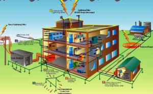
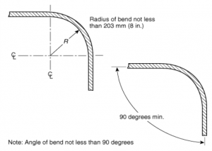
  6. Conductor Bend – No bend of a conductor shall form an included angle of less than 90 degrees, nor shall it have a radius of bend less than 203 mm (8 in.), as shown in figure below.
  7. Each down-comer conductor must terminate at a ground rod dedicated to lightning protection.
  8. The lightning protection ground loop shall be bonded to the electrical system grounding.

lighting protection system installation

Air Terminal Lightning Protection

  1. Review the location layout & detail for each air terminal as per IFC Drawings.
  2. Air terminal shall be not less than 254 mm (10 in.) above the object or area it is to protect.
  3. An air terminal exceeding 600 mm (24 in.) in height above the area or object they are to protect shall be supported at a point not less than one-half their height.
  4. Air terminals shall be secured against overturning or displacement. Install saddle support for each air terminals as per detail.


Read more

FIRE ALARM SYSTEM INSTALLATION PROCEDURE

FIRE ALARM SYSTEM INSTALLATION PROCEDURE

FIRE ALARM SYSTEM INSTALLATION PROCEDURE

Installation of Fire Alarm System Devices

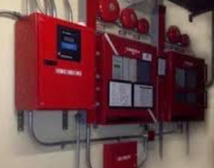
  1. Prior to installations, Identify area classification and verify hazardous areas to be considered during installation activities considering precautionary measures in using tools, equipment and materials to be installed, making sure that all these items are suitable and appropriate as per the area requirements. classifications such as;
    • Substation battery room fixtures and devices shall be enclosed, sealed, vapour tight, corrosion resistant.
    • In hazardous areas enclosure shall met the required classification as per NEC Article 501 or 505 and SAES-P-100.
  2. Ensure that approved installation details, Vendor manuals, project specifications for the specific Fire Alarm system to be installed are fully studied and understood prior to commencing installation.
  3. Check the actual locations and mounting elevation of the devices prior to commencing the installation work.
  4. Installation of fire alarm devices is as per approved detail installation drawing.

Conduit & Fitting Installations for Fire Alarm System

  1. Conduit fittings for outdoor rigid steel conduit shall be cast or forged steel, cast iron or malleable iron, either hot-dip galvanized (preferably), or Zinc electroplated as supplied by approved manufacturer. Refer to SAES-P-104, sec 8.9 para 8.9.1.
  2. Severe corrosive environment are locations and installations listed in sec 9.1 of SAES-P-100. Within three kilometers from the shoreline of the Red Sea vide – SAES-P-100 sec 9.1.3.
  3. As per SAES-P-104 sec 8.9.2. – Conduit fittings for rigid steel conduit and liquid-tight flexible metal conduit used above ground in severe corrosive environments shall be as specified in para 8.9.1 and in addition, shall be protected by one of the following methods:
    1. Factory-coating with PVC (minimum thickness of PVC: 40 mils) per NEMA RN 1. Internal surfaces of PVC sleeves (boots) and other mating PVC surfaces shall be coated with PVC patching compound (1000421977). Uncoated plugs and other bare metal shall be coated with PVC patching compound, or with SAES-H-101 APCS-22 (offshore), or APCS-26 (onshore).
    2. Field-coating prior to installation in accordance with SAES-H-101 APCS-22 (offshore), or APCS-26 (onshore). Light (sweep) sandblasting is required prior to coating so that the zinc is not removed. After installation, any bare metal must be touched up using either of the above coatings, without sandblasting.
    3. By heat-shrinkable tubes or wrap-arounds, where the geometric configuration permits it.
      1. Exception: Red leaded brass or silicon bronze conduit fittings may be used as an alternative to the above in severe corrosive environments (only above ground).
    4. Threads of plugs, coupling, junction boxes and other fittings shall be lightly lubricated with a rust preventive grease such as Crouse Hinds thread lubricant (SAMS No. 14-839-050) or Hi Purity Goop (SAMS No. 26-011-078) before assembly. Refer to SAES-P-104, sec. 8.9 para. 8.9.4.
    5. Fittings for NEMA TC 6 & 8 Type PVC conduit shall be in accordance with NEMA TC 3, TC 9, and TC 3 fittings are generally not interchangeable. Refer to SAES-P-104, sec 8.9 para. 8.9.6.
    6. Survey the conduit routes for possible obstruction and re-routing. Anticipate the possibility of clashing against lighting fixtures, valves, field instruments and related sensitive equipment in the area studying a safe and neat installation.
    7. Install conduit per size indicated on drawing details, conduit layout. The conduit shall be cut square, with ends reamed and where applicable, with sharp and clean cut threads. Apply appropriate thread lubricant for conduit joints connections and put rubber or metallic bushing on conduit ends. Field cut threads and threads cleaned at site on galvanized conduit shall be touched up with cold galvanizing compound, approved by Saudi Aramco.
    8. Verify that conduit threads are properly cut. Conduit shall be cut using cut off wheels, hack saw or roll cutter (pipe cutter). Care should be taken to ensure straight cut.
    9. Conduit shall be securely fastened within 900 mm (3ft) of each outlet box, junction box, device box, cabinet, conduit body, or other conduit termination. Fastening shall be permitted to be increased to distance of 1.5 m (5ft) where structural members do not readily permit fastening within 900 mm (3ft). Where approved conduit shall not be required to be securely fastened within 900mm (3ft) of the service head above the roof termination of a mast. Refer to NFPA 70, NEC Art 344.30 (A).
    10. Conduit shall be supported at intervals not exceeding 3m (10 ft). Refer to NEC Art. 342.30(B) (1).
    11. Provide appropriate plug or cap to conduit system for temporary openings to prevent foreign objects or moisture from entering. All empty conduits shall be left with initial pull wire or a nylon pull cord.
    12. Check the actual routing of the conduits against approved construction drawings.


Read more

error: Content is Protected.