A Single Line Diagram (SLD) in electrical engineering is a simplified graphical representation of a power system or electrical circuit. It uses standardized symbols to depict the various components of the system and their interconnections, all on a single line. The purpose of an SLD is to provide a clear and concise overview of the electrical system’s configuration and layout, allowing engineers and technicians to understand its operation and analyze its performance.
The single line diagram serves as the foundational blueprint for analyzing electrical systems. It’s like a roadmap that provides a clear overview of the entire electrical distribution network within a facility or system. By studying the single line diagram, engineers and technicians can gain comprehensive insights into the layout, design, and interconnections of various components such as generators, transformers, switchgear, and loads.
Single Line Diagram Electrical
Why Single Line Diagram required?
Having an up-to-date single line diagram (SLD) is crucial for the efficient operation and maintenance of electrical systems in any facility of power plants, petrochemical plants and commercial buildings. Here’s why:
- Roadmap for Testing and Maintenance: The SLD serves as a roadmap for all testing, service, and maintenance activities related to the electrical system. It provides a clear and comprehensive overview of the system layout, allowing technicians to quickly locate components and understand their interconnections during maintenance tasks.
- Snapshot of Facility: Similar to a balance sheet, the SLD offers a snapshot of the facility’s electrical infrastructure at a specific moment in time. It reflects the configuration of the electrical system, including all major components and their ratings, ensuring that technicians have accurate information when performing maintenance activities.
- Documentation of Changes: As facilities evolve and undergo modifications or expansions, the SLD needs to be updated accordingly to reflect these changes. By documenting all alterations in a common file, the SLD ensures that the electrical system remains easily understandable for both internal and external technical personnel.
- Support for Engineering Studies: An up-to-date Single Line Diagram is essential for conducting various engineering studies, including short circuit calculations, coordination studies, and load flow studies. It provides the necessary information for analyzing the performance and safety of the electrical system under different operating conditions.
- Electrical Safety: The SLD plays a crucial role in developing and implementing electrical safety procedures within the facility. It helps identify potential hazards, assess risks, and establish safety protocols to protect personnel and equipment from electrical accidents.
- Efficient Maintenance: By providing comprehensive information about the electrical system layout and configuration, an up-to-date SLD facilitates efficient maintenance practices. Technicians can quickly identify critical components, troubleshoot issues, and perform preventive maintenance tasks to ensure the reliability and uptime of the electrical infrastructure.
What Should Be In A Electrical Single Line Diagram (SLD)?
A typical package of a single line diagram should be comprehensive and include the following elements:
- Index, Legend, and Page References: The diagram should begin with an index, legend, and page references for easy navigation and understanding.
- Proper Symbols: All appropriate symbols should be used to represent various components and devices accurately.
- Incoming Lines: Clearly indicate incoming lines, including voltage and size specifications.
- Main Components: Show incoming main fuses, cutouts, switches, and main/tie breakers.
- Power Transformers: Provide details of power transformers, including kVA rating, voltage rating, winding connection, grounding means, % impedance, and cooling type.
- Feeder Breakers and Fused Switches: Include feeder breakers and fused switches with their ratings and types.
- Page References for Circuits: Ensure that all incoming circuits reference the page number from which they originate, and outgoing panels reference the page number to which they connect.
- Relays: Mention the function, use, and type of relays, along with fault current clearing time settings from inverse definite minimum time (IDMT) relays or overcurrent relays (OCRs) of vacuum circuit breaker (VCB) panels.
- Current and Potential Transformers: Specify the size, type, and ratio of current and/or potential transformers.
- Service-Main Cable and Wire Runs: Clearly outline service-main cable and wire runs, along with associated isolating switches.
- Substations and Main Panels: Include all substations, integral relays, and main panels, indicating the total load of each feeder and substation.
- Critical Equipment: Provide details of critical equipment such as UPS, batteries, generators, power distribution, transfer switches, and computer room air conditioning.
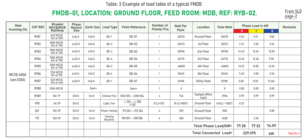
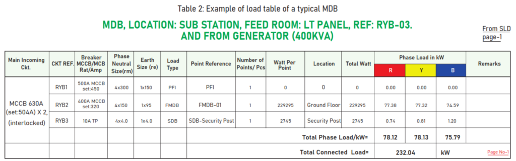
- Load Schedule: Prepare a load schedule for each distribution panel, busbar trunking, or tap-off boxes, specifying the load table format.
- Bus Bar Rating and Dimension: Mention the rating and dimension of bus bars, calculated based on the cross-sectional area.
- Outgoing Cables: Specify outgoing cables with details such as number of cables, number of cores, cable size, and number of poles associated with them.
- Isolating Switches and Protective Devices: Provide information on isolating switches and protective devices, including circuit breakers, fuses, overload relays, and magnetic contactors.
- Set Points and Ratings: Mention the set points of all circuit breakers, thermal overload relays, and ratings of magnetic contactors.
- Cable Laying Length: Include the length of cable laying where no protection is provided for outgoing or incoming circuits.
- PFI, Changeover, ATS, Generators: Properly detail power factor improvement (PFI), changeover, automatic transfer switch (ATS), generators, synchronizers, and interlocking arrangements, along with their ratings and symbols.
- Protective Ratings: Specify all protective ratings of devices for ATS and other protective equipment.
- Earth Conductors: Specify the size, type, and quantity of all earth conductors, including their identification numbers and page references. This information should be provided for transformers, generators, panel boards, and equipment directly connected to earth pits.
- Total Connected Load: Clearly state the total connected load in kilowatts (kW) and specify the individual load capacity (kW) for each connected load.
- Equipment Identification: Identify all connected equipment (loads) with proper marking and include their descriptions. Each load should have a corresponding marking/identification number mentioned in the point reference or load reference column.
- Spare Switches: Mention all spare switches (outgoing circuit breakers) for reference and planning purposes.
- Earthing System: Provide details of the earthing system, excluding lightning protection system (LPS) earth pits. This should include dimensions of the earthing pit, boring, busbar, earth electrode size, earth lead, and earth continuity conductor (ECC) size and type on a separate page.
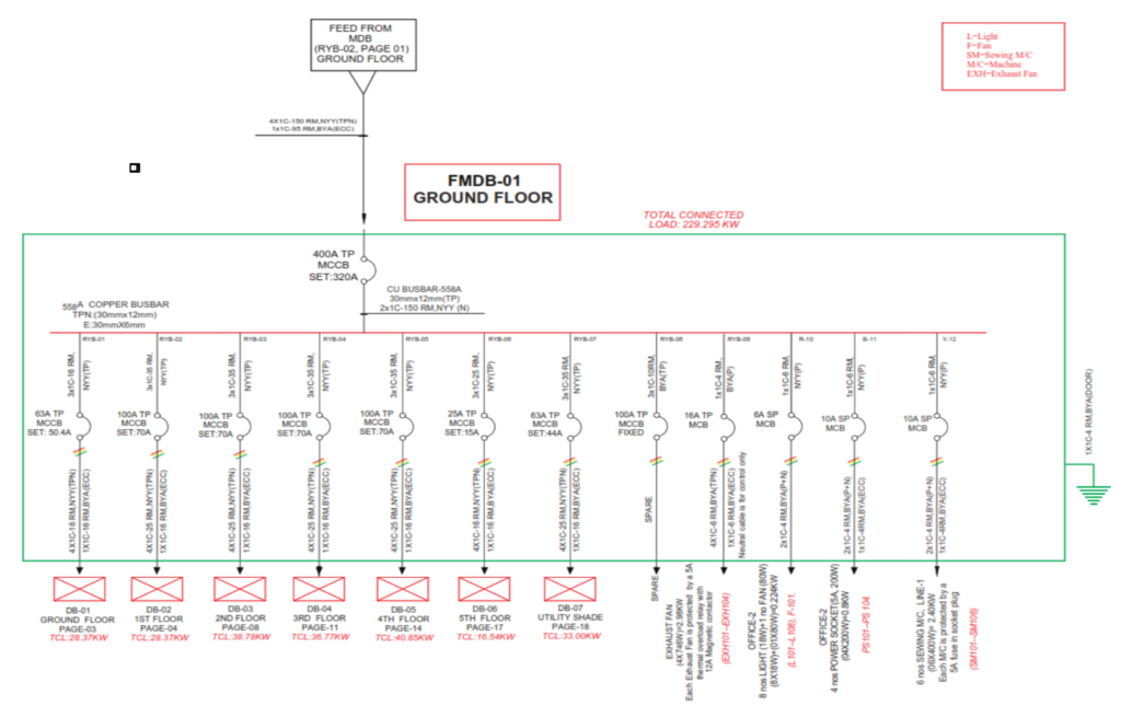
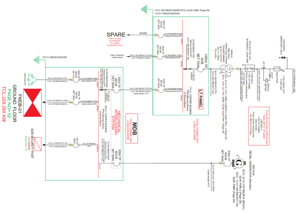
- Example Single-Line Diagram: Include an example of a typical single-line diagram, illustrating the layout of substations, LT panels, distribution panels, and load tables for reference.

Example of Single Line Diagram of typical floor MDB (FMDB)