ELECTRICAL COMMUNICATION SYSTEM PROCEDURE

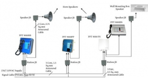
party page station installation

ELECTRICAL COMMUNICATION SYSTEM PROCEDURE

  1. All permanent materials (including fabricated supports), consumables, construction area and resources shall be prepared and checked prior to installation works.
  2. Ensure that all Electrical Equipment and materials, which would suffer damage or deterioration from exposure to the elements has been properly stored indoor, off the ground in suitable warehousing.
  3. Materials and equipment to be installed shall be inspected to ensure the conditions. Should there be factory and handling damages found in the equipment and/or materials,  Subcontractor shall record to QC Material Receiving Inspection report form and immediately inform EPC for disposition.
  4. Ensure that working areas are ready for installation of electrical equipment, properly turned over to Subcontractor Electrical Department by Building subcontractor with a duly accomplished Work Transfer Sheet.
  5. All equipment foundation, base plates, cable entries, oil pits and firewalls (if any) shall be checked for its line and grade against actual dimension of the equipment. Foundation of particular equipment shall be checked to include stub-up prior to acceptance of work transfer sheet. Surveyor shall verify the elevation of the equipment and to be incorporated in the “AS-BUILT” drawings. Any deviations found against AFC drawings, shall be brought to the attention of Company.
  6. Work Transfer Sheet shall be duly signed and processed by other subcontractors or discipline for the preceding works to avoid confusion and discrepancies in the work responsibilities.
  7. Architectural finishing works of the building (needed for selected activities) shall have been completed; in particular, room ventilation, temperature, and humidity level shall be within the limits recommended by the equipment vendor. Indoor equipment to be installed in the building shall be maintained at required room temperature.
  8. Review all references such as the latest Approved for Construction (AFC) drawings, layout, and technical scope of work, work permit requirements, and work procedures including safety standard requirements.
  9. Equipment that has been shipped in sections and/or has loose components shall be identified and checked with corresponding equipment package lists.
  10. Equipment tags shall be identified and scheduled with respect to the latest issued Approved for Construction drawings as well as to the approved milestones schedules.

PAGING SYSTEM INSTALLATION

  1. Survey and study the designed location of paging system
  2. Check locations and provide markings to which elevations, mounting height and orientations should conform in the latest issued Approved for Construction drawings.
  3. Install necessary fabricated supports as required per installation detail. Ensure that the orientation shall comply with the drawing layout.
  4. Verify the installed support against equipment to be installed if suited as per requirements of EPC technical scope of works and latest issued Approved for Construction drawing.
  5. All cabinets shall be correctly leveled and aligned before fastening to the support as per Saudi Aramco specification.
  6. Prior to installation of cable tray underneath tile flooring at Communication room the following item shall be considered.
  • Base plate of cable tray supports shall be anchored at the floor through expansion bolt floor drilling at communication.
  • Align the cable tray supports and ensure that tray routes are accessible starting from end of trench to building cable entry.

7.  Cable tray installation shall be underneath floor tiles at communication room. Complete with fittings and accessories as per requirement.

8. Installation of grounding bus bar to accommodate the possibility of excessed number of grounding cable to be connected from different communication boxes based on the detailed approved for construction drawing.

9. Provide grounding bonding for supports and trays connected to grounding bus bar.

10. QC shall inspect, accept or reject installed cabinet rack and cable tray support.
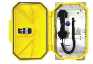
Paging system installation

MAIN AMPLIFIER CABINET INSTALLATION (INDOOR)

  1. Survey and study the designed location of main amplifier cabinet.
  2. Check locations and provide markings to which elevations, mounting height and orientations should conform in the latest issued Approved for Construction Drawings.
  3. Fabricate and install cabinet rack for Main Amplifier cabinet at communication room.
  4. Unload the main amplifier cabinet by utilizing crane equipment.
  5. Uncrate the main amplifier cabinet before moving to communication room.
  6. Pallet truck should have been ready for bringing amplifier cabinet inside the communication room.
  7. All cabinets shall be correctly leveled and aligned before fastening to the support as per Saudi Aramco specification.
  8. Provide grounding bonding for supports and trays connected to grounding bus bar.
  9. QC shall inspect, accept or reject installed cabinet rack and cable tray support.
 

Read more

LIGHTING AND RECEPTACLE INSTALLATION INSIDE BUILDING

LIGHTING AND RECEPTACLE INSTALLATION INSIDE BUILDING

LIGHTING AND RECEPTACLE INSTALLATION INSIDE BUILDING

INSTALLATION OF LIGHTINGS AND DEVICES

  1. Lighting fixtures, devices, junction boxes and its support shall be inspected for possible factory or handling damage and recorded using Quality Control Material Receiving Inspection Report. Where physical damage or non-compliance with the technical scope of work and Saudi Aramco Standards had been found, Subcontractor shall record using Non Conformance Report or Observation Report and report  immediately for company disposition.
  2. Verify the material specification to its conformance with the classification area requirements especially to hazardous areas. This    shall be included in material receiving inspection procedure and to   be recorded in Quality Control Material Receiving Inspection Report  form, which is to be reported immediately to company if non- compliance be found against the materials. Lightings, devices and controls shall comply with SAES-P-123.
  3. Explosion proof identification to the specific material shall be verified with stipulating certifications (if any) as per requirements depending on the intensive usage of the material according to the drawing, as well as area classification.
  4. Survey the location of lightings with reference to layout drawings and details as well as in the given company Technical Scope of Work. Identify area classifications to include hazardous areas in accordance with the latest Approved for Construction drawing.
  5. Categorize and select lighting fittings, devices, junction boxes and related materials to include wattage, types of      fixtures/devices/junction boxes, and type of mounting in accordance  to the company latest approved construction drawing and details, as well as with area classification requirements.
  6. Check that mounting heights are in accordance with the elevations shown on the plan and detail drawings as per C Technical  Scope and Saudi Aramco Standards.
  7. Where manufacturer’s instructions are furnished with the lighting fittings and devices, installation detail shall conform to the  requirement.
  8. Install necessary supports and poles as per detail drawings given, and to the installation standards in accordance with the Project specification and drawing. Ensure that the support is suitable to the lightings/devices materials in consideration to the various environmental classifications stated in layout drawings.
  9. Lighting fittings including lamps, covers, guards and diffusers shall be handled with care to avoid breakage or damage to the fragile parts.
  10. Check the proper position when bringing the fixture to its location   and verify also that overhead clearance, working radius and path are clear from any protruded materials or obstruction.
  11. Mount the lighting fixture and devices in the position, elevation and location as shown on project Approved for Construction drawings.   Location may be varied slightly to avoid piping or structural
  12. The elevation, level and vertical alignment of the lighting fixtures   and devices shall be checked ensuring that it is securely and rigidly fixed in place.
  13. Lighting unit orientation shall be verified ensuring illumination in the area is sufficient and not obstructed by pipes or structures.
  14. Ensure that the conduit to which lighting fittings, devices, and junction boxes were attached are fixed by substantial screws so that the weight of the installed lighting fittings, devices and junction boxes will not be carried by the conduit.
  15. Install conduit per size indicated on drawing details, conduit layout. The conduit shall be cut square, with ends reamed and where applicable, with sharp and clean cut threads. Apply appropriate thread lubricant for conduit joints connections and put rubber or metallic bushing on conduit ends. Field cut threads and threads cleaned at site on galvanized conduit shall be touched up with cold galvanizing compound, approved by Saudi Aramco.
  16. Conduit shall be securely fastened within 900 mm (3ft) of each outlet box, junction box, device box, cabinet, conduit body, or other conduit termination.
  17. After installation following the complete drawing and details, clean the lamps, reflectors, diffusers and housing body. Dust and dirt shall be removed by using appropriate rags.
  18. Terminate all wiring or cable connections according to the termination schedule, installing all termination requirements including identifications required, in which non-corroding material with cable reference numbers, as noted in the cable schedule, are clearly visible. Cabling and wiring works shall be done as   per  SAES-P-104.
  19. Double check all wiring and circuit connections for the lightings/ devices with respect to circuit diagram to avoid possible short-circuiting and damage.


Read more

ELECTRICAL EQUIPMENT INSTALLATION PROCEDURE

ELECTRICAL EQUIPMENT INSTALLATION PROCEDURE

ELECTRICAL EQUIPMENT INSTALLATION PROCEDURE

  1. All permanent materials (including fabricated and pre-fabricated supports), consumables, equipment to be installed and its accessories, construction area and resources shall be prepared and checked prior to installation works.
  2. Ensure that working areas are safe and ready for installation in coordination with other discipline for the use of the area and scaffolding materials.
  3. Work Transfer Sheet shall be duly signed and processed by other subcontractors or discipline for the preceding works to avoid confusion and discrepancies in the work responsibilities.
  4. Study erection procedures of heavy electrical equipment and other sensitive equipment prior to installation.
  5. Special tools shall bear a valid calibration certificates traceable to a national standard indicating calibration validity and periodically (at least six months) checked by a third party laboratory testing facility.
  6. Electrical materials shall conform to all applicable requirements, standard, and specifications prior to release to be used as part of the work. Refer to Schedule “Q” Att. IV Para 7.1.
  7. Review all references such as the latest approved for construction drawings, layout, and Technical Scope of Work.
  8. All equipment related to substation works shall be checked after confirming the availability at company. Visual Inspection shall be conducted for possible factory or handling damage and recorded in appropriate QC Material Receiving Inspection Report form.

STORAGE AND HANDLING OF EQUIPMENT INSTALLATION PROCEDURE

  1. Upon delivery of materials,  QC Inspector will conduct receiving inspection as per Schedule G for Handling and Preservation to verify conformance to vendor drawings. Any deviation shall be documented through a QCIR.
  2. Electrical equipment should be moved and stored in an upright position
  3. Electrical equipment should be stored indoor in a clean dry area as per NFPA 70, NEC Art.110.3 (B) & manufacture recommendation.
  4. Keep sufficient gap between stored materials and equipment for easy access, lifting and moving.
  5. Electrical Equipment should be covered with plastic sheets and all doors should be sealed tight. All equipment parts must be kept in the unopened original shipping case with all braces and plugs intact and shall be covered with plastic sheets.
  6. Air intake openings should remain covered to reduce dust, waster or other unwanted entry accumulation.
  7. Regular visual inspection shall be conducted to check any dust accumulation or dampness on the electrical equipment.
  8. Necessary protection shall be provided in transporting of electrical equipment in accordance with vendor requirements or recommendations and Saudi Aramco standard and specifications.


Read more

WORK PROCEDURE FOR SPLICING AND TERMINATION OF LOW VOLTAGE CABLES

CABLE SPLICING PROCEDURE

WORK PROCEDURE FOR SPLICING AND TERMINATION OF LOW VOLTAGE CABLES

GENERAL PREPARATORY WORKS (SPLICING & TERMINATION)

  1. All permanent materials, consumables, equipment to be installed and its accessories, construction area and resources shall be prepared and checked prior to installation works.
  2. Work Transfer Sheet shall be duly signed and processed by other subcontractors or discipline for the preceding works to avoid confusion and discrepancies in the work responsibilities.
  3. Special tools shall bear a valid calibration certificates traceable to a national standard indicating calibration validity and periodically (at least six months) checked by a company approved third party laboratory testing facility.
  4. Electrical materials shall conform to all applicable requirements, standard, and specifications prior to release to be used as part of the work. Refer to Schedule “Q” Att. IV Para 7.1.
  5. Review all references such as the latest approved for construction drawings, layout, and Technical Scope of Work. Personnel Qualification request for approval shall be submitted 30 days prior to start of the work per Schedule Q para. Attachment IV para 2.1.
  6. Personnel who will perform the termination and splicing shall be approved terminator by the client.
  7. Design and Installation of Wiring and Cable Systems shall be in accordance with the NEC as supplemented by SAES-P-104 and/ or as approved Saudi Aramco Standards.
  8. Cables shall be permanently identified prior to the Splicing / Termination process; Ref SA Std. SAES-P-104 6.10.
  9. The Vendor Instruction Manual requirements shall be incorporated into the installation procedure. NEC 110.3B; Ref SA Std. SAES-P-104 4.1.
  10. All Compression Dies / Connectors shall have a Manufacturer’s Reference compression die number and conductor size normally printed or stamped on the connector as required as SAES-P-104 Para. 6.1.

INSTALLATION WORKS OF CABLES

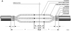
  1. Low voltage cable with damaged outer jacket should be cleaned and free from accumulation of dust, oil, and moisture using required cable cleaning spray and materials.
  2. Make sure that the Low voltage cable with damaged portion is free of sharp edge in order to avoid damage when new wrapped around jacket sleeve is installed.
  3. New wrapped around cable sleeve should be checked if it is cleaned and free from accumulation of dust, oil and moisture. Cleaned the new cable sleeve when required.
  4. In the damaged portion, wrap around the cable of 3M electrical tape, after then wrap the cable with rubber tape and again wrap the cable of 3M electrical tape.
  5. Degrease the ends of the over sheath (new wrapped around cable repair sleeve) for a length of about 150 mm.
  6. Put heat shrink sleeve in centre position and shrink on according to manufactures instruction.
  7. Repeat the Installation Activities Procedure on other portion of medium voltage cable with damaged outer jacket.
  8. Repair of damaged outer jacket of LV Cable shall be as per Manufacturer’s Instructions per NEC 110.3.
  9. All Low Voltage cables shall be installed as per the Company requirement.
  10. Cable shall not be bent sharp to a small radius handling or installation, for cables the minimum bending radius for PVC/XLPE cables shall be 12 times the overall diameter of Cable.
  11. The ends of lead sheathed cable shall be sealed with solder immediately after cutting the cables, in case of PVC cable suitable sealing compounds/ tape shrinkable caps shall be used.


Read more

error: Content is Protected.