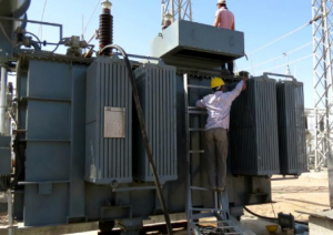
ELECTRICAL TEST TRANSFORMER
Transformer Turns Ratio (TTR) of Transformer
Transformer “turns ratio” must be identical for each phase.
The Turns Ratio = N1/N2 = V1/V2 = I2/I1 = K
Where: N1 = Number of turns of primary windings
N2 = Number of turns of secondary windings
V1 = Primary Voltage (line to line)
V2 = Secondary Voltage (line to neutral)
I1 = Primary Current
I2 = Secondary Current
Turn ratio K = V/V2/√3 = √3 V1/V2 For three phase.
K = V1 / V2 For single phase.
Procedure:
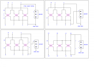
a.) For this test must be conducted between HV winding & LV winding.
b.) For Δ-Y transformer, this test must be conducted between HV winding (line to line) and LV winding (line to neutral).
c.) This test shall be conducted for each winding and all tap setting.
d.) The test value should be noted as under:
Acceptable value:
Turns ratio test result should not deviate more than 0.5% form either the adjacent coil or calculated ratio.
Winding Resistance Test of Transformer
Theory: Resistance of any electrical circuit can be expressed as follows:
R = V/I
Where V = Applied DC voltage
I = Measured DC current
R = Calculated winding resistance in ohm.
Procedure:
For this test, test kit should be connected for both winding in primary and secondary side.
If primary connection between U-V, the Sec. Connection will be between U-V
” V – W “ V – W
“ W – U “ W – U
For single-phase transformer, this connection should be made between (H-H0) and (X-X0)
Acceptable Value:
Winding resistance test results should compare within one percent (1%) of adjacent windings.