RACKS CONSOLE CABINETS INSTALLATION IN PIB

This article is about racks and console cabinets installation in process interface buildings.

Process interface building Installation Activities

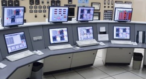
  • Electronic Control System required Installation and Visual Inspection for DCS/ESD 1/0 & CPU Racks and Operator Consoles. Check the actual location and foundation dimensions against the Vendor’s equipment drawings of the equipment’s to be installed.
  • Ensure that the transport of these equipment’s from the laydown yard to the Process Interface Building should be thoroughly Rigging of big equipment’s such as IRP, DCS, ESD 1/0 and CPU Racks should conform to the manufacturer recommendations.
  • From the trailer/ truck using a suitable crane lift down the panels to the cleared staging
  • The panels shall be un-crated in the presence of Contractor and Company Representatives inside the
  • The receiving inspections shall be done in the PIS before i
  • From there using pallet truck assisted by Technician / craftsman each panel shall be moved slowly one-by-one to its temporary location inside the PIS.
  • Layout the actual equipment dimension measurement on the location where the equipment is to be installed.
  • Marked the possible location of equipment’s / panels / racks base support. The location of the equipment should be as approved in I FC
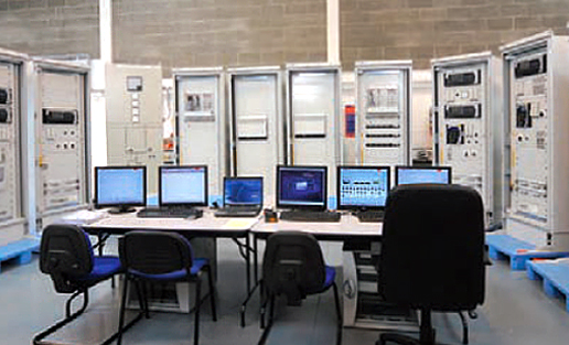
  • In Process Interface Buildings, 3 types of installation will generally be provided is on the base plate, on the raise floor without base plate and the other is on wall mounting.
  • All supports, base plates, floor fixings, penetrations and cable entries shall be checked for its location, alignment, level and overall measurement as against the actual dimension of the equipment’
  • Provide adequate protection to finish floors, walls, and other equipment to prevent accidental damage during the
  • Install the equipment’s/ panels/ racks to its respective location by using pallet truck or tube Always exercise maximum safety in transporting the panels. Pallet truck shall have a greater capacity than Control equipment to be lifted.
  • Mount and anchor the equipment/ panels / racks in accordance with the Vendor manuals and IFC
  • The complete assembly shall be checked to ensure the alignment and level after bolt tightening.
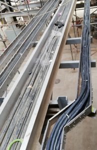
  • Bond the equipment’s/ panels/ racks to its dedicated safety grounding bus-bar as described in SAES-P-111.
  • Vacuum cleaned inside panels / racks to removed dust and any foreign objects.
  • Repair/ touch up paint any damage, scratches on the equipment’s/ panels and racks shall be carried out only by written instruction from system Vendor.

Read more

CONTROL SYSTEM INSTRUMENT EQUIPMENT INSTALLATION

CONTROL SYSTEM INSTRUMENT EQUIPMENT INSTALLATION

Industry Codes and Standards

NEMA ICS                           Enclosures for Industrial Controls and System

IEEE 1100                            Powering and Grounding Sensitive Electronic Equipment

NFPA 70                               National Electrical Code

Definition of Terms

  • DCS – Distributed Control System
  • ESD – Emergency Shutdown System
  • I/O – Input/Output
  • CPU – Central Processor Unit
  • FAT – Factory Acceptance Test
  • FF – Foundation Fieldbus
  • MCT – Multi Cable Transit
  • PIB – Process Interface Building
  • NEMA – National Electrical Manufacturers Association
  • P&ID – Piping and Instrumentation Diagram
  • PLC – Programmable Logic Controller
  • UPS – Uninterruptible Power Supply
  • NEC – National Electric Code
  • MCC – Motor Control Centre
  • CCR – Central Control Room
  • FAS – Fire Alarm System
  • HART – Highway Addressable Remote Transducer
  • SID – Instrument Segment Diagram
  • ILD – Instrument Loop Diagram
  • SIS – Safety Instrumented System
  • SAT – Site Acceptance Test
  • RTD – Resistenace Temperature Detector

PANEL, RACK & DCS CABINET INSTALLATION

  1. DCS control networks shall be based on IEEE 802.3 CSMA/CD (Ethernet) standard. As per 23-SAMSS-10 Sec. 11.1 para. 11.1.1.
  2. Ensure that the transport of this equipment’s from the laydown yard to the Process Interface Building should be thoroughly planned. Rigging    of big equipment’s such as IRP, DCS, ESD I/O and CPU Cabinets    should conform to the manufacturer recommendations.
  3. Panel, rack and cabinet arrangement shall be checked against the relevant Plan Layout and General Arrangement Drawings and the    latest issued and approved for construction drawing
  4. Where supports are required, these shall be installed in accordance with approved detailed construction drawings.
  5. All support assemblies installed in the control room to support panels, cabinets, consoles, tray, etc. shall be constructed prior to panel
  6. Install panels, racks and cabinets based on approved installation drawings, taking consideration all possible obstacles and clearances    requirements per project specification.
  7. Installation of equipments shall be properly plumbed, aligned and fixing bolt tightened. Where equipment consists of a number of panel    sections, the assembly shall commence from the center section.    Sections on either side of the center shall be alternated, leveled and    shimmed as necessary.
  8. Cabinets, consoles and control panels may be installed on raised floor or bolted to dedicated supports as per approved drawing.
  9. The installation of cabinets shall be carried out in accordance with the control room layout and detailed instructions of the manufacturer. It    shall be approved by EPC/COMPANY and conforms to the latest issued approved for construction drawing.
  10. Where multiple section desks or cabinets are used, care shall be taken to ensure that all wiring (disconnected for shipping purposes) are connected and re-clamped to its pre-shipped condition.
  11. All cabinets shall have a nameplate permanently attached.
  12. Marshalling cabinets shall comply with the requirements of 34- SAMSS-820(Saudi Aramco standard), “Instrument Control Cabinets – Indoors.”
  13. System Cabinets: Saudi Aramco 34-SAMSS-820 requirements shall be applied for all wiring, cables, terminal blocks and ways ducts located within DCS system cabinets which are associated with the    following:
      1. Power supply and distribution
      2. Utility power, lighting, and convenience outlets
      3. Intermediate terminal strips for I/O wiring
      4. Grounding

PANEL, RACK & DCS CABINET INSTALLATION

Read more

CABLE TRAY INSTALLATION PROCEDURE

This article is about cable tray installation as per international standard of NEMA VE1, NEMA VE2 and ARAMCO standards.

CABLE TRAY INSTALLATION PROCEDURE / METHOD STATEMENT

1. All cable trays & accessories received at site shall be inspected, handled and stored upon receipt in accordance with Project Procedure for Material Control.

2. Inspections shall be conducted by the Electrical contractor, Electrical QC Inspector and Company representative in accordance with Inspection & Test Plan (ITP) inspection test plan.

3. Cable trays and covers for electrical & instrumentation cables shall be manufactured from hot dip galvanized carbon steel matching to project requirement specifications.

4. Cable tray installation shall be self supporting type with a wide flange (48mm or 72mm or 100mm) in accordance with cable cross section.

5. Cable tray installation shall preferably be installed flat in buildings or operating structures.  Tray shall run as far as possible under flooring and walkways.  Only in special cases shall cable trays be installed vertically or on edge.  On vertical cable trays and on edgewise – horizontal cable trays, each cable shall be fixed with 20mm wide stainless steel strips (two per meter).  On horizontal cable trays, laid flat cables are fixed in group (one fastening for every two or three meters).  On pipe racks, cable tray shall run on the top most level(s).

6.  Cable trays shall be fixed onto standard steel shapes, welded to steel structures or fixed on to concrete structures with self-drilling dowels.  Distance between fixing points and cable tray support spacing shall be a maximum of three meter for ladder type tray and two meter maximum for perforated tray so as to avoid strain on cable trays.

7. Cable tray installation shall be designed to carry a load of 100kg/m. All cable trays shall be perforated or ladder type to avoid the retention of water and to allow fastening of the cables.

8.  Cable trays shall be provided with covers where there is high risk of mechanical damage during normal operation or maintenance periods.  Cover fabrication shall be the same as that of cable trays themselves and shall be fixed on cable trays with proper clips recommended by cable tray Manufacturer/Vendor and comply with project required specification.

9.  The number of single or multi-conductor cables rated 11kV, 6.6kV, 1kV or less in cable trays shall include an allowance of 20% extra space for future expansion.

10.  Separate racking/trays shall be installed for the following electrical systems, generally arranged top to bottom manner.
a.) HV and MV cables
b.) LV Power, Lighting and Control cables for non-instrument cables
c.) Instrument Cables (Electronic and Signal Cables)
d.) Telecommunication Cables

Read more

error: Content is Protected.